Toyota Prius C (from 2011) – fuse box diagram
Year of production: 2011, 2012, 2013, 2014, 2015, 2016
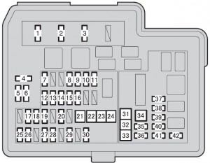
Engine compartment (type A fuse box)
| Fuse | Ampere rating [A] | Circuit | |
| 1 | EFI-MAIN | 20 | Multiport fuel injection system/sequential multiport fuel injection system, EFI NO.2 |
| 2 | HORN | 10 | Horn |
| 3 | IG2 | 30 | IG2 NO.2, METER, IGN |
| 4 | SPARE | 7,5 | Spare fuse |
| 5 | SPARE | 15 | Spare fuse |
| 6 | SPARE | 30 | Spare fuse |
| 7 | EFI NO.2 | 10 | Multiport fuel injection system/sequential multiport fuel injection system |
| 8 | H-LP RH-LO | 10 | Right-hand headlight (low beam) |
| 9 | H-LP LH-LO | 10 | Left-hand headlight (low beam), gauge and meters |
| 10 | H-LP RH-HI | 10 | Right-hand headlight (high beam) |
| 11 | H-LP LH-HI | 10 | Left-hand headlight (high beam), gauge and meters |
| 12 | IG2 NO.2 | 10 | Multiport fuel injection system/sequential multiport fuel injection system, steering switches, brake system, starter system, smart key system, occupant classification system, SRS airbag system |
| 13 | DOME | 15 | Audio system, vehicle control and operation data recording, main body ECU, personal lights, luggage compartment light |
| 14 | ECU-B NO.1 | 7,5 | Main body ECU, smart key system |
| 15 | METER | 7,5 | Gauge and meters |
| 16 | IGN | 15 | Multiport fuel injection system/sequential multiport fuel injection system |
| 17 | HAZ | 10 | Emergency flashers |
| 18 | ETCS | 10 | Multiport fuel injection system/sequential multiport fuel injection system |
| 19 | ABS NO.1 | 20 | Brake system |
| 20 | ENG W/PMP | 30 | Multiport fuel injection system/ sequential multiport fuel injection system |
| 21 | H-LP-MAIN | 40 | H-LP LH-LO, H-LP RH-LO, H-LP LH-HI, H-LP RH-HI, daytime running light system |
| 22 | H-LP CLN | 30 | No circuit |
| 23 | ABS MTR NO.1 | 30 | Brake system |
| 24 | P/I | 50 | EFI-MAIN, HORN, IG2 |
| 25 | ECU-B NO.2 | 7,5 | Air conditioning system, gauge and meters, occupant classification system, tire pressure warning system, starter system, smart key system, power door lock system |
| 26 | AM2 | 7,5 | Starter system |
| 27 | STRG LOCK | 20 | Starter system |
| 28 | ABS NO.2 | 10 | Brake system |
| 29 | IGCT-MAIN | 30 | IGCT NO.2, IGCT NO.3, IGCT NO.4, PCU, BATT FAN |
| 30 | D/C CUT | 30 | DOME, ECU-B NO.1 |
| 31 | PTC HTR NO.1 | 30 | PTC heater |
| 32 | PTC HTR NO.2 | 30 | PTC heater |
| 33 | FAN | 30 | Electric cooling fan |
| 34 | PTC HTR NO.3 | 30 | PTC heater |
| 35 | DEF | 30 | MIR HTR, rear window defogger |
| 36 | DEICER | 20 | No circuit |
| 37 | BATT FAN | 10 | Battery cooling fan |
| 38 | IGCT NO.2 | 10 | Hybrid system |
| 39 | IGCT NO.4 | 10 | Hybrid system |
| 40 | PCU | 10 | Hybrid system |
| 41 | IGCT NO.3 | 10 | Hybrid system |
| 42 | MIR HTR | 10 | Outside rear view mirror defoggers |
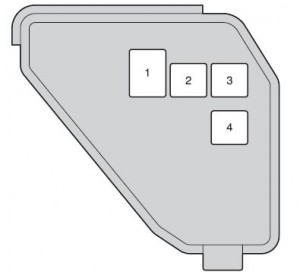
Engine compartment (type B fuse box)
| Fuse | Ampere rating [A] | Circuit | |
| 1 | DC/DC | 100 | Hybrid system |
| 2 | ABS MTR NO.2 | 30 | Brake system |
| 3 | HTR | 40 | Air conditioning system |
| 4 | EPS | 50 | Electric power steering system |
Under the driver’s side instrument panel
WARNING: Terminal and harness assignments for individual connectors will vary depending on vehicle equipment level, model, and market.