Chevrolet Sonic (2018) – fuse box diagram
Year of production: 2018
Engine Compartment Fuse Block
The engine compartment fuse block is located on the driver side of the vehicle, near the battery.
1.8L Engines
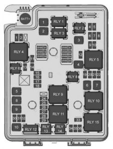
| Mini fuses | Usage |
| 1 | ABS valve |
| 2 | Sunroof |
| 4* | Rear fog lamp |
| 5 | Exterior rearview mirror/Power window switch |
| 6 | Automatic occupant sensing/ROS |
| 7 | Passive entry/Passive start |
| 8 | Regulated voltage control |
| 10 | –/Intelligent battery sensor |
| 11 | Rear window defogger |
| 12 | Electric steering column lock |
| 13* | –/SAI valve |
| 14 | Heated exterior rearview mirror |
| 15 | Front heated seats |
| 16 | Fuel system control module 1 |
| 17 | Canister vent |
| 18 | Washer |
| 19* | Fuel pump |
| 20 | Engine control module 5 |
| 21 | Fuel system control module 2/Leveling |
| 22 | Transmission control module 1/DC DC converter |
| 24 | Engine control module 1 |
| 25 | Coil |
| 26 | Engine control module 4 |
| 27 | Engine control module 3 |
| 28 | Engine control module 2 |
| 29 | Injector/Ignition coil |
| 30 | Engine control module |
| 31 | Air conditioning clutch |
| 32 | Transmission control module |
| 33 | Horn |
| 34 | Front fog lamps |
| 35 | Left high-beam headlamp |
| 36 | Right high-beam headlamp |
| * = If equipped | |
| J-Case fuse | Usage |
| 1 | Front wipers |
| 2 | Antilock brake system pump |
| 3 | Blower |
| 4 | Run/Crank IEC |
| 6 | Cooling Fan K4 |
| 7 | Cooling Fan K5 |
| 8* | SAI pump |
| 9 | Electric vacuum pump |
| 10 | Start |
| * = If equipped | |
| Relays | Usage |
| RLY 1 | Front wiper control |
| RLY 2* | Rear fog lamp |
| RLY 3 | Front wiper speed |
| RLY 4 | Rear defogger |
| RLY 5 | Run/Crank |
| RLY 6* | –/SAI valve |
| RLY 8* | Fuel pump |
| RLY 9* | SAI pump |
| RLY 10 | Cooling fan K3 |
| RLY 11 | P/T |
| RLY 12 | Start |
| RLY 13 | Air conditioning clutch |
| RLY 14 | High-beam headlamps |
| RLY 15 | Cooling fan K1 |
| * = If equipped | |
1.4L Engine
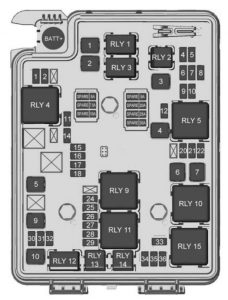
| Mini fuses | Usage |
| 1 | Antilock brake system valve |
| 2 | Sunroof |
| 4* | Rear fog lamp |
| 5 | Exterior rearview mirror/Power window switch |
| 6 | Automatic occupant sensing/ROS |
| 7 | Passive entry/Passive start |
| 8 | Regulated voltage control |
| 9 | Rear wiper |
| 10 | –/Intelligent battery sensor |
| 11 | Rear window defogger |
| 12 | Electric steering column lock |
| 14 | Heated Exterior rearview mirror |
| 15 | Front heated seats |
| 16 | Fuel system control module 1 |
| 17 | Canister vent |
| 18 | Washer |
| 20 | Engine control module 5 |
| 21 | Fuel system control module 2/Leveling |
| 22 | Transmission control module 1/DC DC converter |
| 24 | Engine control module 1 |
| 25 | Coil |
| 26 | Engine Control Module 4 |
| 27 | Engine Control Module 3 |
| 28 | Engine Control Module 2 |
| 29 | Injector/Ignition Coil |
| 30 | Engine control module |
| 31 | Air conditioning clutch |
| 32 | Transmission control module |
| 33 | Horn |
| 34 | Front fog lamps |
| 35 | Left high-beam headlamp |
| 36 | Right high-beam headlamp |
| * = If equipped | |
| J-Case fuse | Usage |
| 1 | Front Wiper |
| 2 | Antilock brake system pump |
| 3 | Blower |
| 4 | Run/Crank IEC |
| 5 | Power seat |
| 6 | Cooling Fan K4 |
| 7 | Cooling Fan K5 |
| 9 | Electric vacuum pump |
| 10 | Start |
| * = If equipped | |
| Relays | Usage |
| RLY 1 | Front wiper control |
| RLY 2* | Rear fog lamp |
| RLY 3 | Front wiper speed |
| RLY 4 | Rear Defogger |
| RLY 5 | Run/Crank |
| RLY 9 | Cooling fan K2 |
| RLY 10 | Cooling Fan K3 |
| RLY 11 | P/T |
| RLY 12 | Start |
| RLY 13 | Air conditioning clutch |
| RLY 14 | High-beam headlamps |
| RLY 15 | Cooling Fan K1 |
| * = If equipped | |
Instrument Panel Fuse Block
The instrument panel fuse block is located on the underside of the driver side instrument panel.
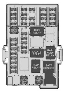
| Fuses | Description |
| DLS | Discrete logic ignition switch |
| DLC | Data Link Connector |
| SDM | Sensing and diagnostic module |
| L/GATE | Liftgate |
| PWR WNDW REAR | Rear power window |
| BCM8 | Body Control Module 8 |
| BCM7 | Body Control Module 7 |
| BCM6 | Body Control Module 6 |
| BCM5 | Body Control Module 5 |
| BCM4 | Body Control Module 4 |
| BCM3 | Body Control Module 3 |
| BCM2 | Body Control Module 2 |
| BCM1 | Body Control Module 1 |
| IPC | Instrument panel cluster |
| TELEMATICS | Telematics |
| PAS/SBSA | Parking assist system/Side blind spot alert system |
| RAIN SNSR | Rain sensing wiper |
| AUDIO | Audio |
| TRAILER1 | Trailer 1 |
| LDW/FCA | Lane departure warning/Front collision alert |
| CGM | Central gateway module |
| HVAC1 | Heating, ventilation, and air conditioning 1 |
| HLLD SW | Automatic headlamp leveling switch |
| IPC/AOS | Instrument panel cluster/Automatic occupant sensing display |
| SPARE | — |
| TRAILER2 | Trailer hitch 2 |
| CLOCKSPRING | Clock spring |
| HVAC2 | Heating, ventilation, and air conditioning 2 |
| HTD STR WHL | Heated steering wheel |
| SPARE | — |
| S/ROOF SW | Sunroof switch |
| CIGAR APO | Cigar auxiliary power outlet |
| ESCL | Electric steering column lock |
| PWR WNDW FRONT | Front power windows |
| IRAP ACCY | IRAP accessory |
| BATT CONN | Battery connector |
| RUN RELAY | Run relay |
| L/GATE RELAY | Liftgate relay |
| IRAP RELAY | IRAP relay |
| RAP/ACCY RELAY | Retained accessory power/Accessory relay |
WARNING: Terminal and harness assignments for individual connectors will vary depending on vehicle equipment level, model, and market.