KIA Soul EV (2016 – 2018) – fuse box diagram
Year of production: 2016, 2017, 2018
Instrument panel (Driver’s side fuse panel)
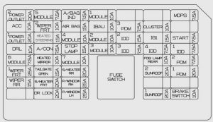
| Description | Ampere rating [A] | Protected component |
| POWER OUTLET 2 | 20 | Front Power Outlet |
| ACC | 10 | BCM, Mood Lamp Module, A/V & Navigation Head Unit, Smart Key Control Module, Power Outside Mirror Switch, E/R Junction Block (Power Outlet Relay) |
| POWER OUTLET 1 | 25 | Rear Power Outlet |
| DRL | 10 | BCM |
| MODULE 6 | 7,5 | Front Seat Warmer Module, Driver Air Ventilation Seat Control Module |
| WIPER FRT 1 | 25 | E/R Junction Block (Front Wiper Low Relay) |
| WIPER RR | 15 | Rear Wiper Motor, Multifunction Switch |
| MODULE 5 | 7,5 | BCM, Smart Key Control Module |
| WIPER FRT 2 | 10 | BCM, Multifunction Switch, PCB Block (Front Wiper High Relay) |
| HEATED STEERING | 15 | Clock Spring (Steering Wheel Heated) |
| A/CON | 7,5 | A/C Control Module, Heater Assembly (Cluster Ionizer) |
| HEATED MIRROR | 10 | A/C Control Module, Driver/Passenger Power Outside Mirror, Rear Defogger |
| TAIL GATE OPEN | 15 | Tail Gate Open Relay |
| S/HEATER FRT | 25 | Front Seat Warmer Module, Driver Air Ventilation Seat Control Module |
| DR LOCK | 20 | Door Lock Relay, Door Unlock Relay, Two Turn Unlock Relay |
| A/BAG IND | 7,5 | Instrument Cluster |
| A/BAG | 15 | SRS Control Module |
| MODULE 4 | 10 | Electro Chromic Mirror, Front Seat Warmer Module, Driver Air Ventilation Seat Control Module |
| STOP LAMP | 15 | Stop Signal Electronic Module |
| MODULE 7 | 10 | Sport Mode Switch, ICM Relay Box |
| S/HEATER RR | 20 | Rear Seat Warmer Module |
| P/WINDOW RH | 25 | Power Window RH Relay |
| P/WINDOW LH | 25 | Power Window LH Relay, Driver Safety Power Window Module |
| MODULE 1 | 10 | BCM |
| IBAU | 10 | Integrated Brake Actuation Unit |
| MODULE 2 | 10 | Tire Pressure Monitoring Module, Crash Pad Switch, Center Fascia Switch, Electronic Parking Brake Module, Stop Lamp Switch, Rear Parking Assist Sensor RH/LH (IN/OUT), Front Parking Assit Sensor LH/RH (OUT/IN) |
| MODULE 3 | 10 | ATM Lever Indicator, Multipurpose Check Connector, PCB Block (IG3 #4 Relay) |
| PDM 3 | 7,5 | Smart Key Control Module |
| IOD2 | 15 | A/V & Navigation Head Unit |
| IOD3 | 7,5 | ICM Relay Box (Outside Mirror Folding Relay, Outside Mirror Unfolding Relay) |
| CLUSTER | 10 | Instrument Cluste |
| IG1 | 15 | EPCU |
| IOD4 | 7,5 | Instrument Cluster, Tire Pressure Monitoring Module, Data Link Connector, Multipurpose Check Connector, A/C Control Module, BCM |
| FOG LAMP REAR | 10 | Rear Fog Lamp Control Block |
| SUNROOF 2 | 20 | SUNROOF_MOTOR (POWER |
| SUNROOF 1 | 20 | SUNROOF_MOTOR(POWER) |
| MDPS | 7,5 | MDPS Unit |
| START | 7,5 | Transaxle Range Switch |
| IOD1 | 7,5 | Overhead Console Lamp, Vanity Lamp LH/RH, Room Lamp, Glove Box Lamp, Luggage Lamp |
| PDM 2 | 7,5 | Smart Key Control Module |
| PDM 1 | 20 | Smart Key Control Module |
| BRAKE SWITCH | 10 | Smart Key Control Module, Stop Lamp Switch |
Motor compartment fuse panel
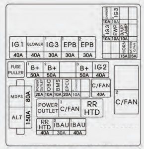
| Description | Ampere rating [A] | Protected component |
| MDPS | 80 | MDPS Unit |
| ALT | 150 | Alternator |
| B+1 | 50 | Smart Junction Block (Fuse – (S/HEATER FRT, TAIL GATE OPEN, DR LOCK, P/WINDOW LH, P/WINDOW RH, MODULE 7)) |
| B+2 | 50 | Smart Junction Block (Fuse – (STOP LAMP) Arisu-LT2) |
| B+3 | 50 | Smart Junction Block (Fuse – (PDM 1, PDM 2, BRAKE SWITCH, Leak Current Autocut Device) IPS1, Arisu-LT1) |
| IG2 | 40 | PCB Block (Button Start (IG2) Relay) |
| POWER OUTLET | 20 | Power Outlet Relay |
| OBC | 10 | OBC Unit, Rear Heated Relay |
| BMS | 10 | BMS Control Module |
| EPCU | 20 | EPCU |
| CHARGER 2 | 10 | Normal Charge Port Lmap |
| C/FAN | 40 | COOLING FAN 1 Relay, COOLING FAN 2 Relay |
| RR HTD | 40 | Rear Heated Relay |
| IBAU 2 | 30 | Integrated Brake Actuation Unit |
| IBAU 1 | 40 | Integrated Brake Actuation Unit |
| IG1 | 40 | Button Start (ACC) Relay, Button Start (IG1) Relay |
| BLOWER | 410 | Blower Relay |
| IG3 1 | 30 | IG3 #1/#2/#3/#4/#5 Relay |
| EPB 1 | 30 | Electronic Parking Brake Module |
| EPB 2 | 30 | Electronic Parking Brake Module |
| IG3 2 | 10 | Blower Relay, A/C Control Module, A/C Compressor, E/R Junction Block (Cooling Fan 1/2 Relay), Heater Assembly (PTC Heater) |
| CHARGER 1 | 10 | OBC Unit, BMS Control Module |
| EWP | 10 | Electronic Water Pump |
| IG3 3 | 15 | EPCU, Transaxle Range Switch, A/V & Navigation Head Unit, Instrument Cluster |
| HORN | 15 | Horn Relay |
| B/UP LAMP | 10 | Transaxle Range Switch, EPCU |
| BATTERY C/FAN | 25 | Battery C/FAN Relay |
| Number | Relay name | Type |
| E41 | Power Outlet Relay | PLUG MICRO |
| E42 | C/FAN 1 Relay | PLUG MICRO |
| E43 | RR HTD Relay | PLUG MICRO |
| E44 | C/FAN 2 Relay | PLUG MINI |
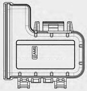
Motor compartment fuse panel (Battery terminal cover)
WARNING: Terminal and harness assignments for individual connectors will vary depending on vehicle equipment level, model, and market