Dodge Sprinter (2008 – 2009) – fuse box diagram
Year of production: 2008, 2009
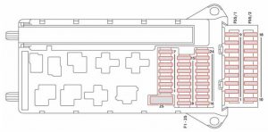
Main fuses box
The fuses box is in the footwell on the lefthand side of the vehicle.
| Number | Consumer | Amp. |
| 1 | Horn | 15 |
| 2 | Electric steering ESTL (electronic ignition switch EIS) | 25 |
| 3 | Terminal 30 Z, vehicle with gasoline engine/electronic ignition switch EIS/ instrument cluster | 10 |
| 4 | Light switch/center console switch unit | 5 |
| 5 | Windshield wipers | 30 |
| 6 | Fuel pump | 15 |
| 7 | MRM (jacket tube module) | 5 |
| 8 | Terminal 87 (2) | 20 |
| 9 | Termina 87 (3) | 20 |
| 10 | Terminal 87 (4) | 10 |
| 11 | Terminal 15 R vehicle | 15 |
| 12 | Airbag control unit | 10 |
| 13 | Cigarette lighter/glove box lighting/radio* | 15 |
| 14 | Diagnostic socket/light switch/instrument cluster | 5 |
| 15 | Front heating system* | 5 |
| 16 | Terminal 87 (1) | 10 |
| 17 | Airbag control unit | 10 |
| 18 | Terminal 15 vehicle, brake lamp switch | 7,5 |
| 19 | Interior lights | 7,5 |
| 20 | Power window passenger’s side/terminal 30/2 signal acquisition and actuation module | 25 |
| 21 | Engine control unit | 5 |
| 22 | Antilock brake system (ABS) | 5 |
| 23 | Starter motor | 25 |
| 24 | Diesel engine components | 10 |
| 25 | 12V socket on the bottom of the center console | 25 |
Fuse block F55/1
| Number | Consumer | Amp. |
| 1 | Control panel, left door | 25 |
| 2 | Diagnostic socket | 10 |
| 3 | Brake system (valves) | 25 |
| 4 | Brake system (delivery pump) | 40 |
| 5 | Terminal 87 (5) | 7,5 |
| 10 | ||
| 6 | Terminal 87 (6) | 7,5 |
| 10 | ||
| 7 | Headlamp cleaning system* | 30 |
| 8 | Anti-theft alarm system (ATA)*/siren* | 15 |
| 9 | Auxiliary indication module* | 10 |
Fuse block F55/2
| Number | Consumer | Amp. |
| 10 | Radio* | 15 |
| 11 | Telephone* | 7,5 |
| 12 | Front blowers/auxiliary heating* blower speed 1 | 30 |
| 13 | Pre-wiring mounting slot (center console)* | 7,5 |
| 14 | Seat heating*/center console switch unit | 30 |
| 15 | Non MB-body electrics | 10 |
| 16 | Heater, rear heating-/air conditioning system, front/CD-player* | 10 |
| 17 | Motion detector*/convenience interior lighting* | 10 |
| 18 | Air conditioning in the rear* | 7,5 |
Preliminary fuse box in the battery recess in the driver’s footwell F59
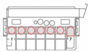
| Number | Consumer | Amp. |
| 1 | Pre-glow relay/secondary air pump | 80 |
| 40 | ||
| 2 | Engine fan air conditioning system – cab chassis/crewcab | 60 |
| 40 | ||
| 3 | Signal acquisition and actuation module SAM/fuse and relay block SRB | 80 |
| 4 | Auxiliary battery*/retader* | 150 |
| 5 | Terminal 30 fuse boxes, signal acquisition and actuation module SAM/fuse and relay block SRB | 150 |
| 6 | Connecting point in driver’s seat base | Bridge |
| 7 | Heater booster (PTC) | 150 |
Fuse box in the driver’s seat
The fuse box is located in the base of the driver’s seat on the outboard side.
WARNING: Terminal and harness assignments for individual connectors will vary depending on vehicle equipment level, model, and market.