Toyota Land Cruiser (2010 – 2011) – fuse box diagram
Year of production: 2010, 2011
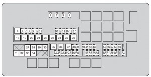
Engine compartment
| Fuse | Ampere rating [A] | Circuit | |
| 1 | A/F | 15 | A/F heater |
| 2 | HORN | 10 | Horn |
| 3 | EFI MAIN | 25 | EFI, A/F heater |
| 4 | IG2 MAIN | 30 | Injector, ignition, meter |
| 5 | RR A/C | 50 | No circuit |
| 6 | SEAT-A/C LH | 25 | No circuit |
| 7 | RR S/HTR | 20 | Rear seat heater |
| 8 | DEICER | 20 | Windshield wiper de-icer |
| 9 | CDS FAN | 25 | Condenser fan |
| 10 | TOW TAIL | 30 | Towing tail |
| 11 | RR P/SEAT | 30 | No circuit |
| 12 | ALT-CDS | 10 | Alternator condenser |
| 13 | FR FOG | 15 | Front fog lights |
| 14 | SECURITY | 5 | Security horn |
| 15 | SEAT-A/C RH | 25 | No circuit |
| 16 | STOP | 15 | Stoplights, high mounted stoplight, brake controller, towing converter, ABS, VSC, main body ECU, EFI |
| 17 | TOW BRK | 30 | Brake controler |
| 18 | RR AUTO A/C | 50 | Rear blower control |
| 19 | PTC-1 | 50 | PTC heater |
| 20 | PTC-2 | 50 | PTC heater |
| 21 | PTC-3 | 50 | PTC heater |
| 22 | RH-J/B | 40 | No circuit |
| 23 | SUB BATT | 40 | Towing |
| 24 | VGRS | 40 | No circuit |
| 25 | H-LP CLN | 30 | Headlight cleaner |
| 26 | DEFOG | 30 | Rear window defogger |
| 27 | AHC | 60 | No circuit |
| 28 | HTR | 50 | Blower controller |
| 29 | PBD | 30 | No circuit |
| 30 | LH-J/B | 150 | Main body ECU |
| 31 | ALT | 180 | No circuit |
| 32 | A/PUMP NO.1 | 50 | AI DRIVER |
| 33 | A/PUMP NO.2 | 50 | AI DRIVER2 |
| 34 | MAIN | 40 | Headlight, daytime running light system |
| 35 | ABS1 | 50 | ABS |
| 36 | ABS2 | 50 | ABS |
| 37 | ST | 30 | Starter system |
| 38 | IMB | 7,5 | ID code box, smart key system, GBS |
| 39 | AM2 | 5 | Main body ECU |
| 40 | DOME2 | 7,5 | Vanity lights, overhead module |
| 41 | ECU-B2 | 5 | Driving position memory system |
| 42 | TEL | 5 | No circuit |
| 43 | RSE | 7,5 | Rear seat entertainment |
| 44 | TOWING | 30 | Towing |
| 45 | DOOR NO.2 | 25 | Main body ECU |
| 46 | STR LOCK | 20 | Steering lock system |
| 47 | TURN-HAZ | 15 | Meter, front turn signal lights, rear turn signal lights, towing converter |
| 48 | EFI MAIN2 | 20 | Fuel pump |
| 49 | ETCS | 10 | EFI |
| 50 | ALT-S | 5 | IC-ALT |
| 51 | AMP | 30 | Audio system |
| 52 | RAD NO.1 | 10 | Navigation system, radio receiver assembly |
| 53 | ECU-B1 | 5 | Smart key system, overhead module, tilt and telescopic steering, meter, cool box, gateway ECU, steering sensor |
| 54 | DOME1 | 5 | Door courtesy lights, clock |
| 55 | HEAD LH | 15 | Headlight high beam (left) |
| 56 | HEAD LL | 15 | Headlight low beam (left) |
| 57 | INJ | 10 | Injector, ignition |
| 58 | MET | 5 | Meter |
| 59 | IGN | 10 | Circuit open, SRS airbag system, gateway ECU, occupant detection system, smart key system, ABS, VSC, steering lock system, GBS |
| 60 | HEAD RH | 15 | Headlight high beam (right) |
| 61 | HEAD RL | 15 | Headlight low beam (right) |
| 62 | EFI NO.2 | 7,5 | AFM, EVP VSV, 02 SSR, KEY OFF PMP, AI DRIVER, AI EX VSV, ACIS VSV |
| 63 | RR A/C NO.2 | 7,5 | No circuit |
| 64 | DEF NO.2 | 5 | Outside rear view mirror heater |
Driver’s side instrument panel
![Toyota Land Cruiser - fuse box - driver' s side instrument panel` class=`size-medium wp-image-8865` height=`103` loading=`lazy` sizes=`(max-width: 300px) 100vw, 300px` src=`/uploads/4b2/c6f/9b7/4b2c6f9b7bfb12eacf0dfd8e1471237e.jpg` srcset=`/uploads/4b2/c6f/9b7/4b2c6f9b7bfb12eacf0dfd8e1471237e.jpg 300w, 768w, 873w` width=`300` />
<figcaption class=`wp-caption-text` id=`caption-attachment-8865`>Toyota Land Cruiser – fuse box – driver’ s side instrument panel</figcaption>
</figure>
<table class=`table table-hover table-bordered`>
<tbody>
<tr>
<td colspan=`2`>Fuse</td>
<td>Ampere rating [A]</td>
<td>Circuit</td>
</tr>
<tr>
<td>1</td>
<td>CIG</td>
<td>15</td>
<td>Cigarette lighter</td>
</tr>
<tr>
<td>2</td>
<td>BK/UP LP</td>
<td>10</td>
<td>Back-up lights, trailer</td>
</tr>
<tr>
<td>3</td>
<td>ACC</td>
<td>7,5</td>
<td>Stereo component amplifier assembly, multi-display assembly, gateway ECU, radio receiver assembly, main body ECU, mirror ECU, rear seat entertainment, smart key system, clock</td>
</tr>
<tr>
<td>4</td>
<td>PANEL</td>
<td>10</td>
<td>Four-wheel drive system, ashtray, cigarette lighter, brake controller, cool box, cruise control, center differential lock, DAC, multi-display assembly, seat heater, air conditioning system, glove box light, emergency flasher, radio receiver assembly, headlight cleaner, inverter, driving position memory system, mirror ECU, overhead module, roll sensing of curtain shield airbags off switch, shift lever switch, steering switches, VSC, console switch</td>
</tr>
<tr>
<td>5</td>
<td>ECU-IG NO.2</td>
<td>10</td>
<td>Air conditioning system, heater, overhead module, ABS, VSC, steering sensor, yaw rate & G sensor, main body ECU, stoplights, moon roof, clock, EC mirror</td>
</tr>
<tr>
<td>6</td>
<td>WINCH</td>
<td>5</td>
<td>No circuit</td>
</tr>
<tr>
<td>7</td>
<td>A/C IG</td>
<td>10</td>
<td>Cool box, condenser fan, cooler compressor, MG CL, rear window defogger, RR MGC VLV</td>
</tr>
<tr>
<td>8</td>
<td>TAIL</td>
<td>15</td>
<td>Tail lights, license plate lights, front fog lights, front side marker lights, rear side marker lights, parking lights</td>
</tr>
<tr>
<td>9</td>
<td>WIPER</td>
<td>30</td>
<td>Windshield wiper</td>
</tr>
<tr>
<td>10</td>
<td>WSH</td>
<td>20</td>
<td>Windshield washer</td>
</tr>
<tr>
<td>11</td>
<td>RR WIPER</td>
<td>15</td>
<td>Rear wiper</td>
</tr>
<tr>
<td>12</td>
<td>4WD</td>
<td>20</td>
<td>4WD</td>
</tr>
<tr>
<td>13</td>
<td>LH-IG</td>
<td>5</td>
<td>Alternator, sub battery, seat heater, windshield wiper deicer, seat belt pretensioners, emergency flasher, inverter, shift lever switch</td>
</tr>
<tr>
<td>14</td>
<td>ECU-IG NO.1</td>
<td>5</td>
<td>ABS, VSC, tilt and telescopic steering, gateway ECU, shift lock system, cruise control system, pre-collision seat belt, headlight cleaner, multi-display assembly, driving position memory system, power door lock system</td>
</tr>
<tr>
<td>15</td>
<td>S/ROOF</td>
<td>25</td>
<td>Moon roof</td>
</tr>
<tr>
<td>16</td>
<td>RR DOOR RH</td>
<td>20</td>
<td>Power windows</td>
</tr>
<tr>
<td>17</td>
<td>MIR</td>
<td>15</td>
<td>Mirror ECU, outside rear view mirror heater</td>
</tr>
<tr>
<td>18</td>
<td>RR DOOR LH</td>
<td>20</td>
<td>Power windows</td>
</tr>
<tr>
<td>19</td>
<td>FR DOOR LH</td>
<td>20</td>
<td>Power windows</td>
</tr>
<tr>
<td>20</td>
<td>FR DOOR RH</td>
<td>20</td>
<td>Power windows</td>
</tr>
<tr>
<td>21</td>
<td>RR FOG</td>
<td>7,5</td>
<td>No circuit</td>
</tr>
<tr>
<td>22</td>
<td>A/C</td>
<td>7,5</td>
<td>Air conditioning system</td>
</tr>
<tr>
<td>23</td>
<td>AM1</td>
<td>5</td>
<td>No circuit</td>
</tr>
<tr>
<td>24</td>
<td>TI & TE</td>
<td>15</td>
<td>Tilt and telescopic steering</td>
</tr>
<tr>
<td>25</td>
<td>FR P/SEAT RH</td>
<td>30</td>
<td>Front seat adjustment</td>
</tr>
<tr>
<td>26</td>
<td>PWR OUTLET</td>
<td>15</td>
<td>Power outlet</td>
</tr>
<tr>
<td>27</td>
<td>OBD</td>
<td>7,5</td>
<td>DLC3</td>
</tr>
<tr>
<td>28</td>
<td>PSB</td>
<td>30</td>
<td>Pre-collision seat belt</td>
</tr>
<tr>
<td>29</td>
<td>DOOR NO.1</td>
<td>25</td>
<td>Main body ECU</td>
</tr>
<tr>
<td>30</td>
<td>FR P/SEAT LH</td>
<td>30</td>
<td>Front seat adjustment</td>
</tr>
<tr>
<td>31</td>
<td>INVERTER</td>
<td>15</td>
<td>Inverter</td>
</tr>
</tbody>
</table>
<h3>Passenger’s side instrument panel</h3>
<figure aria-describedby=`caption-attachment-8869` class=`wp-caption alignnone` id=`attachment_8869` style=`width: 300px`><img alt=`Toyota Land Cruiser - fuse box - passenger's side instrument panel](/uploads/54c/aaa/247/54caaa247e095aef00e77bfe2923a5a4.jpg)
| Fuse | Ampere rating [A] | Circuit | |
| 1 | RSF LH | 30 | No circuit |
| 2 | B/DR CLSR RH | 30 | No circuit |
| 3 | B/DR CLSR LH | 30 | No circuit |
| 4 | RSF RH | 30 | No circuit |
| 5 | DOOR DL | 15 | No circuit |
| 6 | AHC-B | 20 | No circuit |
| 7 | TEL | 5 | Multimedia |
| 8 | TOW BK/UP | 7,5 | Towing |
| 9 | AHC-B NO.2 | 10 | No circuit |
| 10 | ECU-IG NO.4 | 5 | Tire pressure warning system |
| 11 | SEAT-A/C FAN | 10 | No circuit |
| 12 | SEAT-HTR | 20 | Seat heater |
| 13 | AFS | 5 | No circuit |
| 14 | ECU-IG NO.3 | 5 | No circuit |
| 15 | TV | 10 | Multi-display assembly |
WARNING: Terminal and harness assignments for individual connectors will vary depending on vehicle equipment level, model, and market.