Scion xB (2004 – 2007) – fuse box diagram
Year of production: 2004, 2005, 2006, 2007
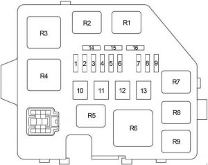
Passenger Compartment
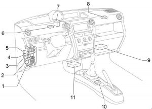
| Number | Description |
| 1 | Instrument Panel J/B |
| 2 | Fuse Block |
| 3 | Front Fog Light Relay |
| 4 | Headlight Relay |
| 5 | Rear Window Defogger Relay |
| 6 | Door Control Receiver |
| 7 | Door Lock Control Relay |
| 8 | A/C Amplifier |
| 9 | Engine Control Module |
| 10 | Shift Lock Control SW |
| 11 | Airbag Sensor Assembly |
Passenger Compartment Fuse Box
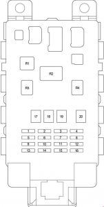
| Fuse | Ampere rating [A] | Circuit | |
| 1 | GAUGE | 10 | Back−up lights, charging system, air conditioning system, power window system, gauges of meters |
| 2 | — | — | — |
| 3 | D/L | 25 | Power door lock system |
| 4 | TAIL | 10 | Tail lights, parking lights, license plate lights |
| 5 | — | — | — |
| 6 | WIPER | 20 | Windshield wipers and washer |
| 7 | ECU−B | 7,5 | SRS airbag system |
| 8 | FOG | 15 | Front fog lights |
| 9 | ACC | 15 | Clock, cigarette lighter |
| 10 | ECU−IG | 7,5 | Anti−lock brake system, electric cooling fan |
| 11 | OBD | 7,5 | On−board diagnosis system |
| 12 | HAZ | 10 | Turn signal lights, emergency flashers |
| 13 | A.C | 7,5 | Air conditioning system |
| 14 | — | — | — |
| 15 | — | — | — |
| 16 | STOP | 10 | Stop lights, high mounted stop light, anti−lock brake system, shift lock system, multiport fuel injection system/sequential multiport fuel injection system |
| 17 | AM1 | 40 | “ACC”, “GAUGE”, “WIPER”, and “ECU−IG” fuses |
| 18 | POWER | 30 | Power windows |
| 19 | HTR | 40 | Air conditioning system |
| 20 | DEF | 30 | Rear window defogger system |
| Relay | |||
| R1 | Air conditioning system | ||
| R2 | Flasher | ||
| R3 | Power windows | ||
| R4 | Circuit Opening Relay | ||
| Number | Fuse | Ampere ratting [A] | Description |
| 18 | I/UP | 7,5 | Rear window defogger system, multiport fuel injection system/ sequential multiport fuel injection system |
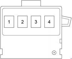
Engine Compartment
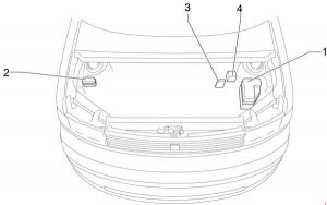
| Number | Description |
| 1 | Fuse Box |
| 2 | Additional Relay Box |
| 3 | Fusible Link Block |
| 4 | Skid Control ECU with Actuator |
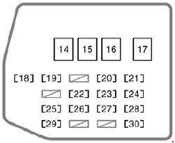
Engine Compartment Fuse Box
| Fuse | Ampere rating [A] | Circuit | |
| 1 | DOME | 15 | Clock, interior light, gauges of meters |
| 2 | EFI | 15 | Multiport fuel injection system/sequential multiport fuel injection system |
| 3 | HORN | 15 | Horn |
| 4 | AM2 | 15 | Starter system, SRS airbag system, multiport fuel injection system/sequential multiport fuel injection system, discharge warning system |
| 5 | ST | 30 | Starter system |
| 6 | — | — | — |
| 7 | H−LP LH H−LP LO LH |
10 | Left−hand headlight |
| 8 | H−LP RH H−LP LO RH |
10 | Right−hand headlight |
| 9 | A/C2 | 7,5 | Air conditioning system |
| 10 | — | — | — |
| 11 | RDI | 30 | Electric cooling fan |
| 12 | HTR SUB1 | 50 | Air conditioning system |
| 13 | ABS NO.1 | 40 | Anti−lock brake system |
| 14 | SPARE | 30 | Spare |
| 15 | SPARE | 15 | Spare |
| 16 | — | — | — |
| Relay | |||
| R1 | Electric cooling fan (No.1) | ||
| R2 | Electric cooling fan (No.2) | ||
| R3 | Starter | ||
| R4 | — | ||
| R5 | — | ||
| R6 | Heater (A/C) | ||
| R7 | EFI | ||
| R8 | — | ||
| R9 | Horn | ||
Fusible Link Block
| Number | Fuse | Ampere ratting [A] | Description |
| 1 | — | — | — |
| 2 | MAIN | 60 | ABS, TRAC and VSC Charging Combination Meter Electronically Controlled Transmission and A/T Indicator Engine Control Seat Belt Warning (From Dec. 2005 Production) SRS Starting and Ignition |
| 3 | ALT | 120 | ABS, TRAC and VSC Charging |
| 4 | ABS | 60 | ABS, TRAC and VSC |
Additional Relay Box
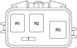
| Number | Fuse | Ampere ratting [A] | Description |
| 1 | — | — | — |
| Relay | |||
| R1 | — | ||
| R2 | ABS | ||
| R3 | ABS | ||
WARNING: Terminal and harness assignments for individual connectors will vary depending on vehicle equipment level, model, and market.