Chevrolet Volt (2013) – fuse box diagram
Year of production: 2013
Engine compartment
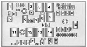
| Mini fuses | Usage |
| 1 | Engine Control Module – Switched Power |
| 2 | Emissions |
| 3 | — |
| 4 | Ignition Coils/Injectors |
| 5 | Column Lock |
| 6a | Column Lock |
| 6b | Rear Demister |
| 7 | — |
| 8 | — |
| 9 | Heated Mirrors |
| 10 | Air Conditioning Control Module |
| 11 | Traction Power Inverter Module – Battery |
| 12 | — |
| 13 | Cabin Heater Pump and Valve |
| 14 | Theft Deterrent – Power Sounder (If Equipped) |
| 15 | Traction Power Inverter Module and Transmission Control Module – Battery |
| 17 | Engine Control Module – Battery |
| 22 | Left Main-Beam Headlamp |
| 24 | — |
| 25 | — |
| 26 | Theft Deterrent – Horn (If Equipped) |
| 31 | — |
| 32 | Run/Crank – Sensing Diagnostic Module, Instrument Cluster, Passenger Airbag Display, Headlamp Level Switch, Automatic Dimming Inside Rearview Mirror (If Equipped) |
| 33 | Run/Crank – Vehicle Integration Control Module |
| 34 | Vehicle Integration Control Module – Batter |
| 35 | — |
| 36 | Power Electronics Coolant Pump |
| 37 | Cabin Heater Control Module |
| 38 | Rechargeable Energy Storage System (High Voltage Battery) Coolant Pump |
| 39 | Rechargeable Energy Storage System (High Voltage Battery) Control Module |
| 40 | Front Windscreen Washer |
| 41 | Right Main-Beam Headlamp |
| 46 | — |
| 47 | — |
| 49 | — |
| 50 | Run/Crank – Rear Vision Camera, Accessory Power Module, Tyre Pressure Monitor, Headlamp Levelling Motors (If Equipped) |
| 51 | Run/Crank for ABS/Rechargeable Energy Storage System (High Voltage Battery) |
| 52 | Engine Control Module/Transmission Control Module – Run/Crank |
| 53 | Traction Power Inverter Module – Run/Crank |
| 54 | Run/Crank – Fuel System Control Module, Air Conditioning Control Module, On-Board Charger |
| J-case fuse | Usage |
| 16 | — |
| 18 | — |
| 19 | Power Window – Front |
| 20 | — |
| 21 | Antilock Brake System Electronic Control Unit |
| 23 | Charge Port Door |
| 27 | — |
| 28 | — |
| 29 | — |
| 30 | Antilock Brake System Motor |
| 42 | Cooling Fan – Right |
| 43 | Front Wipers |
| 44 | Charger |
| 45 | — |
| 48 | Cooling Fan – Left |
| Mini Relays | Usage |
| 3 | Powertrain |
| 4 | Heated Mirrors |
| 7 | — |
| 9 | — |
| 11 | — |
| 12 | — |
| 13 | — |
| 14 | Run/Crank |
| Micro Relays | Circuit |
| 1 | — |
| 2 | — |
| 6 | — |
| 8 | — |
| 10 | — |
| Ultra Micro Relays | Circuit |
| 5 | Charge Port Door |
Instrument Panel Fuse box (Left Side)
The left instrument panel fuse box is on the left side end of the instrument panel.
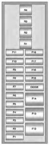
instrument panel (left side)
| Fuses | Usahe |
| F1 | Power Outlet – Top of IP Storage Bin |
| F2 | Radio |
| F3 | Instrument Cluster (LHD)/Hands-Free Phone (RHD) |
| F4 | Infotainment Display |
| F5 | Heating, Ventilation & Air Conditioning/Integrated Centre Console Switches |
| F6 | Airbag (Sensing Diagnostic Module) |
| F7 | Data Link Connector, Left (Primary LHD), Data Link Connector, Left (Secondary RHD) |
| F8 | Column Lock (LHD) |
| F9 | GSM (OnStar Data Only) |
| F10 | Body Control Module 1/Body Control Module Electronics/Keyless Entry/Power Moding/Centre High-Mounted Stop lamp/License Plate Lamps/Left Daytime Running Lamp/Left Position Lamps/Tailgate Release Relay Control/Washer Pump Relay Control/Switch Indicator Lights |
| F11 | Body Control Module 4/Left Headlamp |
| F12 | Fan (RHD) |
| F13 | — |
| F14 | — |
| F15 | Power Outlet (Inside Floor Console/Rear of Floor Console) |
| F16 | — |
| F17 | — |
| F18 | — |
| Relays | Usage |
| R1 | Retained Accessory Power Relay for Power Outlets |
| R2 | — |
| R3 | — |
| R4 | Deadbolt (If Equipped LHD), Child Lockout (RHD) |
| Diodes | Circuit |
| DIODE | — |
Instrument Panel Fuse box (Right Side)
The right instrument panel fuse box is on the right side end of the instrument panel.
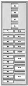
instrument panel (right side)
| Fuses | Usage |
| F1 | Steering Wheel Switch Back lighting |
| F2 | Column Lock (RHD) |
| F3 | Cluster (RHD)/Hands-Free Phone (LHD) |
| F4 | Body Control Module 3/Right Headlamp |
| F5 | Body Control Module 2/Body Control Module Electronics/Tailgate Lamp/Right Daytime Running Lamp/Shifter Lock/Switch Back lighting/Rear Fog Lamp |
| F6 | Body Control Module 5/Retained Accessory Power Relay Control/Right Front Turn Signal Lamp/Left Rear Stop and Turn Signal Lamp/Right Position Lamps/Remote PRNDL |
| F7 | Body Control Module 6/Map Lights/Courtesy Lights/Back-up Lamp |
| F8 | Body Control Module 7/Left Front Turn Signal/Right Rear Stop and Turn Signal Lamp/Child Security Lock Relay Control |
| F9 | Body Control Module 8/Locks |
| F10 | Data Link Connector, Right (Secondary LHD), Data Link Connector, Right (Primary RHD) |
| F11 | Intrusion and Inclination Sensor (If Equipped) |
| F12 | Fan Motor (LHD) |
| F13 | — |
| F14 | — |
| F15 | — |
| F16 | — |
| F17 | — |
| Relays | Usage |
| R1 | — |
| R2 | — |
| R3 | — |
| R4 | Deadbolt (If Equipped RHD), Child Lockout (LHD) |
| Diodes | Usage |
| DIODE | — |
Rear compartment fuse block
The rear compartment fuse box is on the left side of the rear compartment behind a removable cover.
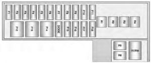
rear compartment
| Fuses | Usage |
| F1 | — |
| F2 | Fuel System Control Module |
| F3 | Passive Start/Passive Entry Module |
| F4 | Heated Seats (If Equipped) |
| F5 | Driver Door Switches (Outside Rearview Mirror/ Charge Port Door Release/Refuel Request/Driver Window Switch) |
| F6 | Fuel (Diurnal Valve and Evap. Leak Check Module) |
| F7 | Accessory Power Module Cooling Fan |
| F8 | Amplifier (If Equipped) |
| F9 | Digital Audio Broadcast (If Equipped) |
| F10 | Regulated Voltage Control/Ultrasonic Front and Rear Parking Assist (If Equipped) |
| F11 | Horn |
| F12 | Rear Power Windows |
| F13 | Electric Parking Brake |
| F14 | Rear Demist (Upper Grid) |
| F15 | — |
| F16 | Tailgate Release |
| F17 | — |
| F18 | — |
| Relays | Usage |
| R1 | Rear Demist (Upper Grid) |
| R2 | Tailgate Release |
| R3 | — |
| R4 | — |
| R5 | — |
| R6 | — |
| R7 | Horn |
| R8 | Horn |
| Diodes | Usage |
| DIODE | — |
WARNING: Terminal and harness assignments for individual connectors will vary depending on vehicle equipment level, model, and market.