Buick Encore (2016) – fuse box diagram
Year of production: 2016
Engine Compartment Fuse Block
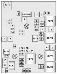
| Mini Fuses | Usage |
| 1 | Sunroof |
| 2 | Outside Rearview Mirror Switch |
| 3 | Canister vent solenoid |
| 4 | Not used |
| 5 | Electronic brake control module valve |
| 6 | Intelligent battery sensor |
| 7 | Not used |
| 8 | Transmission control module battery |
| 9 | Not used |
| 10 | Fuel System Control Module R/C/ Headlamp Leveling |
| 11 | Rear wiper |
| 12 | Rear window defogger |
| 13 | Not used |
| 14 | Outside Rearview Mirror Heater |
| 15 | Fuel system control module battery |
| 16 | Heated seat module/ Memory module |
| 17 | Transmission Control Module R/C |
| 18 | Engine Control Module R/C |
| 19 | Fuel pump |
| 20 | Not used |
| 21 | Fan Relay (Auxiliary Fuse Block) |
| 22 | Not used |
| 23 | Ignition coil/ Injector |
| 24 | Washer pump |
| 25 | Not used |
| 26 | Canister Purge Solenoid/Water Valve Solenoid/ Oxygen Sensors – Pre and Post/Turbo Wastegate Solenoid (1.4L)/Turbo Bypass Solenoid (1.4L) |
| 27 | Auxiliary Heater Pump |
| 28 | Engine Control Module Powertrain Ignition 1 |
| 29 | Engine Control Module Powertrain Ignition 2 |
| 30 | Mass Air Flow Sensor |
| 31 | Left high-beam headlamp |
| 32 | Right high-beam headlamp |
| 33 | Engine control module battery |
| 34 | Horn |
| 35 | Air Conditioning Compressor Clutch |
| 36 | Front fog lamps |
| J-Case Fuses | Usage |
| 1 | Electronic brake control module pump |
| 2 | Front wipe |
| 3 | Blower Motor |
| 4 | IEC RC |
| 5 | Not Used |
| 6 | Not Used |
| 7 | Starter Solenoid (Automatic Transmission), Not Used (Manual Transmission |
| 8 | Cooling Fan Low/Mid |
| 9 | Cooling Fan High |
| 10 | EVP |
| 11 | Pinion Starter Solenoid (Automatic Transmission), Starter Solenoid (Manual Transmission) |
| U-Micro Relays | Usage |
| 2 | Fuel pump |
| 4 | Starter/Spare |
| HC-Micro Relays | Usage |
| 7 | Starter/Starter pinion |
| Mini Relays | Usage |
| 1 | Run/Crank |
| 3 | Cooling fan – mid |
| 5 | Powertrain relay |
| 8 | Cooling fan – low |
| HC-Mini Relays | Usage |
| 6 | Cooling fan – high |
Auxiliary Fuse Block
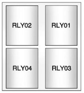
| Relays | Usage |
| RLY01 | Electric vacuum pump |
| RLY02 | Cooling fan control 1 |
| RLY03 | Cooling fan control 2 |
| RLY04 | N/A |
Instrument Panel Fuse Block
The instrument panel fuse block is on the underside of the driver side instrument panel.
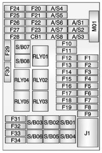
| Fuses | Usage |
| F1 | Body control module 1 |
| F2 | Body control module 2 |
| F3 | Body control module 3 |
| F4 | Body control module 4 |
| F5 | Body control module 5 |
| F6 | Body control module 6 |
| F7 | Body control module 7 |
| F8 | Body control module 8 |
| F9 | Discrete logic ignition switch |
| F10 | Sensing Diagnostic Module Battery |
| F11 | Data link connector |
| F12 | Heater, Ventilation, and Air Conditioning MDL/ICS |
| F13 | Liftgate relay |
| F14 | UPA Module |
| F15 | LDW Module/Inside Rearview Mirror |
| F16 | Adaptive forward lighting module |
| F17 | Power WNDWSW DR |
| F18 | Rain Sensor |
| F19 | Body Control Module Regulated Voltage Contro |
| F20 | Steering Wheel Switch Backlighting |
| F21 | A/C Accessory Power Outlet/ PRND |
| F22 | Cigar Lighter/DC Accessory Power Outle |
| F23 | Spare |
| F24 | Spare |
| F25 | Spare |
| F26 | Automatic Occupant Sensing Display |
| F27 | IPC/PTC Control/ Clutch Switch |
| F28 | Headlamp Switch/ AFL/DC Converter |
| F29 | Spare |
| F30 | Transmission Control Module Battery |
| F31 | IPC Battery |
| F32 | Radio/Chime/ Aux Jack |
| F33 | Display/Faceplate |
| F34 | OnStar/UHP/DAB |
| Midi Fuses | Usage |
| M01 | PTC |
| S/B Fuses | Usage |
| S/B01 | Spare |
| S/B02 | Spare |
| S/B03 | Power Window Motor Front |
| S/B04 | Power Window Motor Rear |
| S/B05 | Logistic mode relay |
| S/B06 | Spare |
| S/B07 | Spare |
| S/B08 | Spare |
| Circuit Breaker | Usage |
| CB1 | Spare |
| Relay | Usage |
| RLY01 | Accessory/Retained accessory power |
| RLY02 | Liftgate |
| RLY03 | Spare |
| RLY04 | Spare |
| RLY05 | Logistic mode |
Rear Compartment Fuse Block
The rear compartment fuse block is behind a cover on the driver side of the rear compartment.
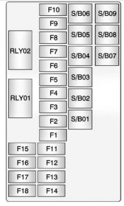
| Mini Fuses | Usage |
| F1 | Driver Seat Power Lumbar Switch |
| F2 | Passenger Seat Power Lumbar Switch |
| F3 | Amplifier |
| F4 | Trailer Socket (N/A) |
| F5 | All-Wheel Drive Module |
| F6 | Automatic Occupant Sensing Module |
| F7 | Spare/LPG Module Battery |
| F8 | Trailer Parking Lamps (N/A) |
| F9 | Spare |
| F10 | Spare/Side Blind Zone Alert Module |
| F11 | Trailer Module (N/A) |
| F12 | Nav Dock |
| F13 | Heated Steering Wheel |
| F14 | Trailer Socket (N/A) |
| F15 | Spare/EVP Switch |
| F16 | Water In Fuel Sensor |
| F17 | Inside Rearview Mirror/Rear Vision Camera |
| F18 | Spare/LPG Module Run/Crank |
| S/B Fuses | Usage |
| S/B01 | Driver Power Seat Switch/Memory Module |
| S/B02 | Passenger Power Seat Switch |
| S/B03 | Trailer Module (N/A) |
| S/B04 | A/C-D/C Inverter |
| S/B05 | Battery |
| S/B06 | Headlamp Washer |
| S/B07 | DC/DC Source 1 |
| S/B08 | DC/DC Source 1 |
| S/B09 | Spare |
| Relays | Usage |
| RLY01 | Ignition Relay |
| RLY02 | Run Relay |
WARNING: Terminal and harness assignments for individual connectors will vary depending on vehicle equipment level, model, and market.