Ferrari California (2008 – 2014) – fuse box diagram
Year of production: 2008, 2009, 2010, 2011, 2012, 2013, 2014
Location
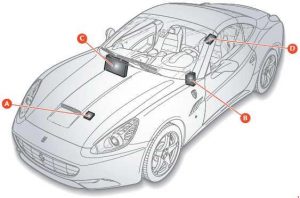 Ferrari California – fuse box diagram – location
| Number |
Description |
| A |
Fuses and relays in engine compartment |
| B |
Body computer fuses and relayu |
| C |
Fuses and relays in passenger compartment on passenger side |
| D |
Fuses and relays in passenger compartment in center console |
Body Computer fuses and relays
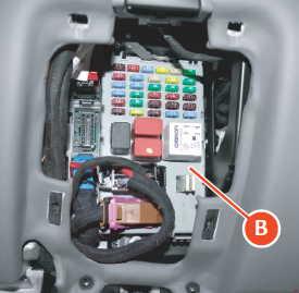 Ferrar California – fuse box diagram – body computer
| Number |
Fuse rating [A] |
Description |
| F12 |
15 |
Right high beam |
| F13 |
15 |
Left high beam |
| F31 |
7,5 |
AC unit, body computer connector |
| F32 |
10 |
Dome lights, foot well and puddle lights, side markers, supplementary taillights. |
| F35 |
7,5 |
Clutch pedal control. Cruise control. Power steering. Beams. |
| F36 |
10 |
Satellite alarm system, parking sensors, fuel filler flap. |
| F37 |
10 |
Stop light control. |
| F38 |
15 |
Luggage compartment lock |
| F39 |
15 |
Radio, diagnosis socket, CAN box interface. |
| F40 |
30 |
Heated rear screen |
| F42 |
7,5 |
Alternator |
| F43 |
30 |
Windscreen wipers |
| F44 |
20 |
Passenger seat heating, cigarette lighter |
| F46 |
20 |
Hard top |
| F47 |
30 |
Driver-side door |
| F48 |
30 |
Passenger-side door |
| F49 |
7,5 |
Passenger compartment lighting switches and controls |
| F50 |
7,5 |
Air bags |
| F51 |
7,5 |
Semi-automatic gearbox, engine start button |
| F52 |
15 |
Power socket driver seat heating |
| F53 |
10 |
Instrument panel |
| Relay |
| T01 |
20 |
Low beam relay |
| T11 |
30 |
Heated rear screen relay |
| T12 |
30 |
Relay services 1 |
| T13 |
— |
Supply jumper services 2 |
Passenger side fuses and relays
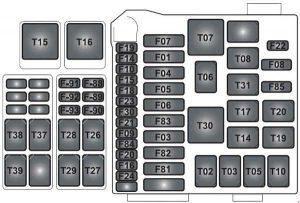 Ferrari California – fuse box diagram – passenger side
| Number |
Ampere ratting [A] |
Description |
| F01 |
60 |
+30 Radiator fans (first speed) |
| F02 |
30 |
+30 ABS (valves) |
| F03 |
30 |
+30 Ignition switch |
| F04 |
50 |
+30 ABS (pump) |
| F05 |
40 |
+30 Air conditioning and heating system |
| F06 |
50 |
+30 Radiator fans (second speed) |
| F07 |
20 |
+30 Horns |
| F08 |
7,5 |
Air conditioning and heating system compressor |
| F09 |
7,5 |
+30 Supplementary stop lights |
| F10 |
15 |
+30 luggage compartment lock relay |
| FII |
25 |
Left bank oxygen sensors |
| F14 |
15 |
+30 high beams |
| F15 |
7,5 |
+30 alternator sensing |
| F16 |
25 |
+30 Right bank engine control power supply |
| F17 |
25 |
+30 Left bank engine control power supply |
| F18 |
10 |
+30 Left cylinder bank injection system power supply, LH cylinder bank injection main relay |
| F19 |
10 |
+30 Right cylinder bank injection system power supply, RH cylinder bank injection main relay coil |
| F20 |
30 |
+30 right injection system main relay |
| F21 |
15 |
+30 Fuel pump 2 |
| F22 |
15 |
Left bank (ignition coil) |
| F23 |
10 |
+30 ABS (electronic) |
| F24 |
15 |
Right bank (ignition coil) |
| F30 |
30 |
+30 Starting relay |
| F81 |
40 |
+30 Supplementary ECU power supply |
| F82 |
70 |
+30 Dashboard ECU and luggage compartment ECU power supply |
| F83 |
50 |
+30 Air pump relay |
| F84 |
15 |
+30 Fuel pump relay 1 |
| F85 |
25 |
Headlight washer |
| F87 |
25 |
Right bank oxygen sensors |
| F88 |
10 |
+15 left cylinder bank injection system |
| F93 |
30 |
+30 suspension control node fuse |
| Relay |
| T02 |
30 |
High beam relay |
| T05 |
30 |
Fuel pump relay 2 |
| T06 |
30 |
Luggage compartment lock actuator relay |
| T07 |
50 |
Horn relay |
| T08 |
30 |
Air conditioning and heating system compressor relay |
| T09 |
30 |
Left cylinder bank injection system main relay |
| T10 |
30 |
Right cylinder bank injection system main relay |
| T14 |
30 |
Fuel pump relay 1 |
| T15 |
50 |
Radiator fan relay (second speed) |
| T16 |
50 |
Radiator fan relay (first speed) |
| T17 |
10 |
INT/A relay (devices excluded at ignition) |
| 20 |
| T19 |
30 |
Stop light control relay |
| T20 |
30 |
Starting relay |
| T26 |
30 |
Windscreen wiper relay (first speed) |
| T27 |
30 |
Windscreen wiper relay (second speed) |
| T28 |
30 |
Windscreen washer pump relay |
| T29 |
30 |
Supplementary stop light relay (third stop light) |
| T30 |
50 |
Air pump relay |
| T37 |
30 |
Left supplementary taillight relay |
| T38 |
30 |
Left headlight LED module power supply |
| T39 |
30 |
Right headlight LED module power supply |
| T31 |
30 |
Headlight washer pump relay |
Fuses and relays on centre console
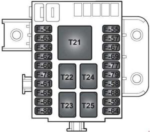 Ferrari California – fuse box diagram – centre console
| Number |
Fuse rating [A] |
Description |
| F54 |
20 |
+30 HI-FI amplifier |
| F56 |
30 |
+30 Driving position |
| F57 |
7,5 |
Side Markers 1 (LH front and RH rear) |
| F59 |
7,5 |
Reverse lights |
| F60 |
30 |
+30 Passenger position |
| F61 |
7,5 |
+30 Driving position (electronic) |
| F62 |
7,5 |
+30 Passenger position (electronic) |
| F63 |
15 |
+30 Semi-automatic gearbox main relay |
| F64 |
7,5 |
Fuel filler flap actuator |
| F65 |
20 |
Door lock actuator |
| F66 |
7,5 |
+30 Semi-automatic gearbox |
| F67 |
7,5 |
Side Markers 2 (RH front and LH rear) |
| F78 |
15 |
+30 Battery charger |
| F80 |
30 |
+30 BassBox amplifier |
| Relay |
| T21 |
50 |
Side Marker relay |
| T22 |
30 |
Reverse light relay |
| T23 |
30 |
Fuel filler flap relay |
| T24 |
30 |
Supplementary taillight relay |
| T25 |
30 |
Semi-automatic gearbox main relay |
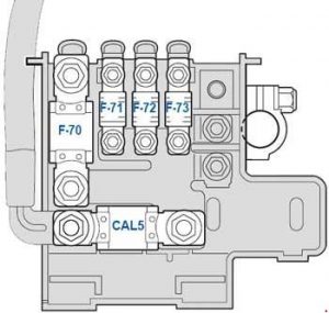
Fuses and relays in the engine compartment
 Ferrari California – fuse box diagram – engine compartment
| Number |
Fuse rating [A] |
Description |
| CAL2 |
CAL2 |
Power sitpply (starter motor and alternator). |
| F70 |
150 |
Power sitpply and engine relay |
| F71 |
40 |
Hard top pump |
| F72 |
40 |
Parking brake power |
| F73 |
70 |
Dashboard ECU power |
WARNING: Terminal and harness assignments for individual connectors will vary depending on vehicle equipment level, model, and market.