Buick Regal (1996) – fuse box diagram

Year of production: 1996

Instrument Panel Fuse Block

Some fuses are located in a fuse block on the passenger’s side of the instrument panel.
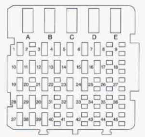
Buick Regal mk3 - fuse box - instrument panel
Buick Regal mk3 – fuse box – instrument panel


Circuit Breakers Usage
C Power Windows
D Power Seat


Fuses Usage
1 CIGAR LIGHTER — Instrument Panel Cigarette Lighter
3 DRL MDL
4 HVAC #2 — HVAC Control Assembly, Solenoid Box
5 HAZARD FLASHER
6 POWER ACCESSORY #2 — Sunroof Control Unit
7 LOCK CONTROL — Door Lock Relay
10 I/P ELECTRONICS BATTERY FEED — Chime Module, Electronic Brake Control Module (EBCM), Theft-Deterrent Module, Radio, Radio Amplifier, Trip Computer
11 STARTER RELAY
12 ANTI-THEFT — Theft-Deterrent Module
13 ABS — Electronic Brake Control Module (EBCM), ABS Relay
14 HVAC BLOWER MOTOR — Blower Motor Relay
15 HVAC #1 — Air Temperature Valve Motor: Trip Computer, Daytime Running Lamps Module (DRL), HVAC Control Assembly, Multifunction Lever Cruise Control Switch
16 REAR DEFOG — HVAC Control Assembly Rear Window Defogger Switch
19 POWER ACCESSORY #1 — Antenna Relay, Power Mirror Switch, Door Lock Switches, Door Handle Switches, Trunk Courtesy Lamp
21 AIR BAG SYSTEM
23 STOPLAMPS — TCC/Brake Switch
24 CRUISE CONTROL
28 CTSY LAMPS — Vanity Mirrors, T/P Courtesy Lamps, I/P Compartment Lamp, Header Courtesy and Reading Lamp, I/S Lighted Rearview Mirror, Dome and Reading Lamps, Quarter Courtesy Lamps
29 WIPER — Wiper Switch
30 TURN SIGNAL — Turn Signal Flasher
32 POWER LOCKS — Door Lock Relay
37 AUXILIARY POWER
38 RADIO — Radio, Steering Wheel Radio Switches
39 I/P ELECTRONICS IGNITION FEED — Headlamp Switch, Cruise Control Cut-Out Switch, Air Bag System, TCC/Brake Switch, Instrument Cluster, Chime Module, Second-Gear Start Switch, Daytime Running Lamps Module (DRL)

Underhood Electrical Center — Passenger’s Side

Some fuses and relays are located in the underhood fuse block on the passenger’s side of the vehicle in the engine compartment.
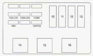
Buick Regal mk3 - fuse box - engine compartment (passeneger's side)` class=`size-medium wp-image-10874` height=`184` loading=`lazy` sizes=`(max-width: 300px) 100vw, 300px` src=`/uploads/b8d/611/12f/b8d61112fbc7602dd9149fb782bd09ba.jpg` srcset=`/uploads/b8d/611/12f/b8d61112fbc7602dd9149fb782bd09ba.jpg 300w,  481w` width=`300` />

<figcaption class=`wp-caption-text` id=`caption-attachment-10874`>Buick Regal mk3 – fuse box – engine compartment (passeneger’s side)</figcaption>
</figure>

<table class=`table table-hover table-bordered`>
	<tbody>
		<tr>
			<td style=`width: 41px;`>Fuses</td>
			<td style=`width: 446px;`>Usage</td>
		</tr>
		<tr>
			<td style=`width: 41px;`>R/CMPT REL</td>
			<td style=`width: 446px;`>Remote Trunk Release</td>
		</tr>
		<tr>
			<td style=`width: 41px;`>ECM BAT</td>
			<td style=`width: 446px;`>Powertrain Control Module (PCM), Fuel Pump, Fuel Pump Relay, Fan Cont #1 Relay</td>
		</tr>
		<tr>
			<td style=`width: 41px;`>A/C CONT</td>
			<td style=`width: 446px;`>A/C CMPR Relay (VIN M only)</td>
		</tr>
		<tr>
			<td style=`width: 41px;`>TCC</td>
			<td style=`width: 446px;`>Automatic Transaxle, Transaxle Range Switch</td>
		</tr>
		<tr>
			<td style=`width: 41px;`>F/IN J N</td>
			<td style=`width: 446px;`>Fuel Injectors</td>
		</tr>
		<tr>
			<td style=`width: 41px;`>ECM IGN</td>
			<td style=`width: 446px;`>Powertrain Control Module (PCM), EGR, CCP, VAPSW, Mass Air Flow (MAF) Sensor (VIN X only), Oxygen Sensor, Vac Canister Switch, Fan #2 Relay</td>
		</tr>
		<tr>
			<td style=`width: 41px;`>ELEK IGN</td>
			<td style=`width: 446px;`>Electronic Ignition (EI) Control Module</td>
		</tr>
		<tr>
			<td style=`width: 41px;`>10</td>
			<td style=`width: 446px;`>I/P Fuse Block</td>
		</tr>
		<tr>
			<td style=`width: 41px;`>11</td>
			<td style=`width: 446px;`>FAN CONT #I Relay</td>
		</tr>
		<tr>
			<td style=`width: 41px;`>12</td>
			<td style=`width: 446px;`>Passenger’s Side Underhood Electrical Center and I/P Fuse Blocks: Fuses 5, 14,23 and 32</td>
		</tr>
		<tr>
			<td style=`width: 41px;`>13</td>
			<td style=`width: 446px;`>FAN CONT #2 Relay and UP Fuse Block: Fuse 16, Power Seat Circuit Breaker “D”</td>
		</tr>
	</tbody>
</table>

<p> </p>

<table class=`table table-hover table-bordered`>
	<tbody>
		<tr style=`height: 24px;`>
			<td style=`width: 41px; height: 24px;`>Relays</td>
			<td style=`width: 446px; height: 24px;`>Usage</td>
		</tr>
		<tr style=`height: 24px;`>
			<td style=`width: 41px; height: 24px;`>14</td>
			<td style=`width: 446px; height: 24px;`>FUEL PUMP</td>
		</tr>
		<tr style=`height: 24px;`>
			<td style=`width: 41px; height: 24px;`>15</td>
			<td style=`width: 446px; height: 24px;`>A/C CMPR</td>
		</tr>
		<tr style=`height: 24px;`>
			<td style=`width: 41px; height: 24px;`>16</td>
			<td style=`width: 446px; height: 24px;`>FAN CONT #2 — Secondary Cooling Fan (Passenger Side)</td>
		</tr>
		<tr style=`height: 24px;`>
			<td style=`width: 41px; height: 24px;`>17</td>
			<td style=`width: 446px; height: 24px;`>FAN CONT #I — Primary Cooling Fan (Driver Side)</td>
		</tr>
		<tr style=`height: 24px;`>
			<td style=`width: 41px; height: 24px;`>18</td>
			<td style=`width: 446px; height: 24px;`>Ignition Relay</td>
		</tr>
	</tbody>
</table>

<h3>Underhood Electrical Center — Passenger’s Side</h3>

<p>Additional fuses are in the underhood electrical center on the driver’s side of the engine compartment.</p>

<figure aria-describedby=`caption-attachment-10875` class=`wp-caption alignnone` id=`attachment_10875` style=`width: 300px`><img alt=`Buick Regal mk3 - fuse box - engine compartment (driver's side)
Buick Regal mk3 – fuse box – engine compartment (driver’s side)
Fuses Usage
PARK LPS Headlamp Switch
HORN Horn Relay, Underhood Lamp
VAR P/S EVO Steering
ABS Anti-Lock Brake System
10 IGN SW2 — I/P Fuse Block: PWR WDO and Circuit Breaker “D”; Passenger’s Side Underhood Electrical Center: TCC and ENG EMIS Fuses
11 IGN SW1 — I/P Fuse Block: Radio, Wiper, HVAC, ABS and Turn Signal Fuses; Passenger’s Side Underhood Electrical Center: F/IJN, ECM IGN and ELEK IGN Fuses
12 HD LPS — Circuit Breaker to Headlamp Switch
13 ABS — ABS Relay


Relay Usage
14 ABS — Anti-Lock Brake System
16 HORN

WARNING: Terminal and harness assignments for individual connectors will vary depending on vehicle equipment level, model, and market.

Обговорення