VW Passat B4 (1993 – 1996) – fuse box diagram
Year of production: 1993, 1994, 1995, 1996
Fuse box

Fuse arrangement according to the numbers on fuse panel from left to right)
| Fuse | Ampere rating [A] | Circuits protected |
| 1 | 10 | Headlight, low beam, left |
| 2 | 10 | Headlight, low beam, right |
| 3 | 10 | Instrument panel lights, license plate lights |
| 4 | 15 | Rear window wiper (wagon) |
| 5 | 15 | Windshield wiper/washer |
| 6 | 20 | Fresh air fan |
| 7 | 10 | Side marker and taillights, right |
| 8 | 10 | Side marker and taillights, left |
| 9 | 20 | Rear window defogger |
| 10 | — | Open |
| 11 | 10 | Headlight, high beam, left |
| 12 | 10 | Headlight, high beam, right |
| 13 | 10 | Horn |
| 14 | 15 | Back-up lights, heated windshield washer nozzles |
| 15 | 10 | Deceleration fuel cut-off, fuel pump after run |
| 16 | 15 | Instrument cluster lights, glove compartment light |
| 17 | 10 | Emergency flashers |
| 18 | 20 | Fuel pump, oxygen sensor heater |
| 19 | 30 | Radiator cooling fan, A/C relay |
| 20 | 10 | Brake lights |
| 21 | 15 | Interior lights, cigarette lighter, digital clock |
| 22 | 10 | Radio |
Relay location on fuse/relay panel
| R1 | A/C relay |
| R2 | Rear window wiper (wagon) |
| R3 | Open |
| R4 | Load reduction relay |
| R5 | Low coolant level control unit |
| R6 | Emergency flasher relay |
| R7 | Open |
| R8 | Intermittent wash wipe relay |
| R9 | Seat belt warning system control unit |
| R10 | Open |
| R11 | Horn relay |
| R12 | Fuel pump relay |
| Separate relays above fuse/relay panel | |
| R13 | Back-up light fuse (auto. trans.) |
| R14 | Radiator cooling fan after run control unit |
| R15 | ABS hydraulic pump relay |
| R16 | ABS relay |
| R17 | Open |
| R18 | Open |
| R19 | A/C relay |
| R20 | Starter cut-outback-up light relay |
| R21 | ABS hydraulic pump fuse/power window fuse |
| R22 | ABS valves fuse |
| R23 | Cruise control fuse/automatic shoulder belt system fuse |
| R24 | Open |
Connections and plugs on fuse/relay panel
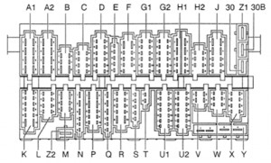
| Symbol | Description |
| A1 | Headlight wiring harness (yellow) |
| A2 | Headlight wiring harness (yellow) |
| B | Open |
| C | Headlight wiring harness (yellow) |
| D | Optional equipment wiring harness (green) |
| E | Instrument wiring harness (green) |
| F | Engine compartment wiring harness, right (white) |
| G1 | Engine compartment wiring harness, right (white) |
| G2 | Engine compartment wiring harness, right (white) |
| H1 | Steering column switch wiring harness (red) |
| H2 | Steering column switch wiring harness (red) |
| J | Steering column switch wiring harness (red) |
| K | Rear wiring harness (black) |
| L | Rear wiring harness (black) |
| M | Rear wiring harness (black) |
| N | A/C wiring harness (green) |
| P | Rear window defroster wiring harness (blue) |
| Q | Instrument wiring harness (blue) |
| R | Light switch wiring harness (blue) |
| S | Engine compartment wiring harness, right (white) |
| T | Two-point connector (green) |
| U1 | Instrument cluster wiring harness (blue) |
| U2 | Instrument cluster wiring harness (blue) |
| V | Multi-function indicator wiring hamess (green) |
| W | Six-point connector (green) |
| X | Warning lamp wiring harness (green) |
| Y | Single connector, terminal 30 |
| Z1 | Single connector |
| Z2 | Single connector, terminal 31 |
| 30 | Single connector, terminal 30 |
| 30B | Single connector |
| 31 | Single connector, terminal 31 |
WARNING: Terminal and harness assignments for individual connectors will vary depending on vehicle equipment level, model, and market.