Ford Taurus (1995 – 1999) – fuse box diagram
Year of production: 1995, 1996, 1997, 1998, 1999
Passenger Compartment Fuse Panel
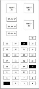
| Number | A | Description |
| 1 | — | — |
| 2 | 5 | Instrument Illumination |
| 3 | 10 | Left Low Beam Headlamp |
| 4 | 10 | Right Low Beam Headlamp |
| 5 | 5 | Instrument Cluster, Shift Lock Actuator, Rear Defrost |
| 6 | 15 | TR Sensor, Reverse Lamps, Daytime Running Lamps, A/C Controls, MLPS switch, Speed Control |
| 7 | 10 | TR Sensor, Starter Relay, MLPS switch |
| 8 | 5 | Power Antenna, Radio Control Unit, GEM |
| 9 | 10 | ABS, Central Temperature Monitor |
| 10 | 20 | PCM Relay, Ignition Coil, Radio, Passive Anti-Theft System |
| 11 | 5 | Instrument Cluster, Air Bag Indicator |
| 12 | 5 | Instrument Cluster, Autolamps, Transmission Control Switch, Integrated Control Panel, GEM |
| 13 | 5 | Electronic Crash Unit (ECU), Blower Motor, Air bag, Electronic Automatic Temperature Control |
| 14 | 5 | Semi-Active Ride Control Module, Lamp Outage Indication |
| 15 | 10 | Multifunction Switch (Turn Signal) |
| 16 | — | — |
| 17 | 30 | Front Wiper/Washer |
| 18 | 5 | Headlamp Switch |
| 19 | 15 | Rear Wiper/Washer |
| 20 | 5 | Integrated Control Panel, Remote Entry, Phone, GEM |
| 21 | 20 | Cigar Lighter |
| 22 | 5 | Power Mirrors, Power Antenna, Luggage Compartment Lamp, Autolamp |
| 23 | 5 | GEM, Wiper system, Variable Assist Steering, Remote Entry, Anti-Theft |
| 24 | 5 | RCC, Speedometer, Integrated Control Panel, Electronic Automatic Temperature Control Module |
| 25 | 10 | Data Link Connector (DLC) |
| 26 | 15 | Luggage Compartment |
| 27 | 10 | Battery Saver Relay |
| 28 | 15 | Speed Control, Brake Lamp |
| 29 | 15 | Multifunction Switch, (Hazard) |
| 30 | 15 | High Beams, Daytime Running Lamps, Instrument Cluster |
| 31 | 5 | Tail Lamp Feed |
| 32 | 10 | Integrated Control Panel, Heated Mirrors |
| 33 | 5 | Power Windows, Lock Illumination |
| Relay | ||
| 34 | Battery Saver Relay | |
| 35 | Driver Door Unlock Relay | |
| 36 | Rear Defroster Relay | |
| 37 | Interior Lamp Relay | |
| 38 | One Touch Window Down Relay | |
| 39 | Accessory Delay Relay | |
Fuse Box In The Engine Compartment (1995-1996)
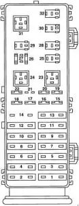
| Number | A | Description |
| 1 | 40 | Junction block |
| 2 | 30 | EEC power |
| 3 | 40 | Ignition |
| 4 | 30 | Power locks |
| 5 | 40 | Ignition |
| 6 | 30 | Power seats |
| 7 | 40 | Rear window defrost |
| 8 | 30 | Thermactor pump |
| 9 | 40 | Cooling fan |
| 10 | 20 | Fuel pump |
| 11 | 40 | Blower motor |
| 12 | 20 | Semi-active suspension |
| 13 | 40 | ABS module |
| 14 | 20 | Radio |
| 15 | 15 | Datime running lamps |
| 16 | 10 | Air bag |
| 17 | 20 | Radio |
| 18 | 30 | Headlamps |
| 19 | 15 | Horn |
| 20 | 15 | Park lamps |
| 21 | — | — |
| 22 | 30 | Headlamps |
| 26 | 30 | Alternator |
| 27 | 10 | Hego power |
| Relay | ||
| 23 | Blower motor relay | |
| 24 | Wiper park relay | |
| 25 | Wiper hi/lo relay | |
| 28 | Washer motor relay | |
| 29 | Horn relay | |
| 30 | Autolamp headlamp relay | |
| 31 | Starter relay | |
| 32 | Autolamp park relay | |
Fuse Box In The Engine Compartment (1997-1999)
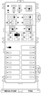
| Number | A | Description |
| 1 | 40 | Junction block |
| 2 | 30 | PCM Relay |
| 3 | 40 | Ignition Switch, Starter Relay |
| 4 | 30 | Accessory Delay Relay, Power Seat |
| 5 | 40 | Ignition Switch |
| 6 | — | — |
| 7 | 40 | Rear Window Defrost Relay |
| 8 | 30 | Thermactor Air ByPass Solenoid, EAM Solid State Relay |
| 9 | 40 | High Speed Cooling Fan Relay, Low Speed Cooling Fan Relay |
| 10 | 20 | Fuel Pump Relay |
| 11 | 40 | Blower Motor Relay |
| 12 | 20 | Semi-Active Ride Control Module |
| 13 | 40 | Anti-Lock Brake Module |
| 14 | — | — |
| 15 | 15 | Daytime Running Lamps (DRL) Module |
| 16 | 10 | Electronic Control Unit (ECU) |
| 17 | 20 | Rear Control Unit, CD Changer |
| 18 | 30 | Anti-Lock Brake Module |
| 19 | 15 | Horn Relay, Powertrain Control Module (PCM) |
| 20 | 15 | Headlamp Switch, Autolamp Park Relay |
| 21 | — | — |
| 22 | 30 | Autolamps Relay, Multifunction Switch, Headlamp Switch |
| 26 | — | A/C Clutch Relay |
| 27 | 10 | A/C Clutch Relay |
| 28 | 15 | Heated Oxygen Sensors, Canister Vent |
| Relay | ||
| 23 | Blower motor relay | |
| 24 | Starter Relay | |
| 29 | Fuel Pump Relay | |
| 30 | PCM Relay | |
| 31 | Low Speed Cooling Fan Relay | |
| Diode | ||
| 32 | PCM Diode | |
| 33 | A/C Clutch Diode | |
| 34 | — | |
WARNING: Terminal and harness assignments for individual connectors will vary depending on vehicle equipment level, model, and market.