Hyundai Veloster (2012 – 2014) – fuse box diagram
Year of production: 2012, 2013, 2014
Instrument panel?
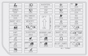
| Fuse name | Symbol | Ampere rating [A] | Protected component |
| C/LIGHTER | 15 | Cigarette Lighter | |
| DRL | 10 | DRL Relay | |
| INVERTER1 | 10 | DC-DC Converter, DC-DC Converter (AMP), Smart Key Control Module | |
| MDPS | 10 | EPS Control Module | |
| A/BAG IND | 10 | Instrument Cluster | |
| POWER OUTLET | 15 | Power Outlet | |
| WIPER RR | 15 | E/R Fuse & Relay Box (RLY. 5), Rear Wiper Motor, Multifunction Switch | |
| IG2 | 10 | E/R Fuse & Relay Box (RLY. 10, RLY. 3), Crash Pad Switch, Panaroma Sunroof Motor, A/C Control Module | |
| WIPER FRT | 25 | Multifunction Switch, Front Wiper Motor, E/R Fuse & Relay Box (RLY. 10) | |
| CLUSTER | 10 | Instru]ment Cluster, Tire Pressure Monitoring Module, Sport Mode Switch | |
| AUDIO2 | 10 | Power Outside Mirror Switch, AMP, A/V & Navigation Head Unit, DC-DC Converter, DC-DC Converter (AMP), Smart Key Control Module | |
| MULTIMEDIA | 15 | DC-DC Converter, A/V & Navigation Head Unit | |
| A/BAG | 15 | PAB ON/OFF IND. & SBR Switch, SRS Control Module | |
| IG1 | 10 | Rear Parking Assist Sensor LH/RH, Rear Parking Assist Sensor LH/RH (Center), Rear Parking Assist Buzzer, SBR Switch, Head Lamp Leveling Device Switch, Driver/Passenger Seat Warmer, Driver/Passenger Seat Warmer Switch, Driver Seat Warmer Module, Head Lamp Leveling Device Actuator LH/RH | |
| SMART KEY1 | 15 | Smart Key Control Module | |
| MEMORY | 10 | Data Link Connector, Instrument Cluster, A/C Control Module | |
| A/CON | 10 | ECM | |
| ABS | 10 | ESP Control Module, ESP OFF Switch, E/R Fuse & Relay Box (RLY. 14, Multipurpose Check Connector) | |
| DR LOCK | 20 | Door Lock Relay, Door Unlock Relay, Flasher Sound Relay, Tail Gate Latch Relay, Dead Lock Relay (RHD) | |
| FOLD’G MIRR/FOG LAMP RR | 15 | Power Outside Mirror Switch, Rear Fog Lamp Relay | |
| STOP LAMP | 15 | Stop Lamp Switch, Key Solenoid, Stop Signal Relay, Smart Key Control Module | |
| ECU1 | 10 | Immobilizer Module, Smart Key Control Module, ECM, Stop Lamp Switch | |
| AMP | 25 | AMP, DC-DC Converter (AMP) | |
| INVERTER2 | 10 | — | |
| INTERIOR LAMP | 10 | Luggage Lamp , Map Lamp, Room Lamp, Vanity Lamp LH/RH, Overhead Console Lamp, Glove Box Lamp | |
| SMART KEY2 | 10 | Smart Key Control Module, Immobilizer Module, Start Stop Button Switch | |
| TCU/* (VACUUM PUMP) | 15 | TCM | |
| TAIL LAMP LH | 10 | Rear Combination Lamp LH, License Lamp LH/RH, ATM Lever Indicator,Instrument Cluster, Multifunction Switch, Passenger Power Window Switch, Power Window Main Switch, AUX & USB Jack, A/C Control Module, ESP OFF Switch, A/V & Navigation Head Unit, Crash Pad Switch, Driver/Passenger Seat Warmer Switch, Head Lamp Leveling Device Switch, Head Lamp LH | |
| S/HEATER | 20 | Driver Seat Warmer Module, Driver/Passenger Seat Warmer | |
| P/WDW LH | 25 | Rear Power Window Switch LH, Power Window Main Switch | |
| START | 10 | Burglar Alarm Relay, Transaxle Range Switch, ECM, E/R Fuse & Relay Box (RLY. 8), TCM | |
| B/UP LAMP1 | 15 | Back-Up Lamp Switch, Transaxle Range Switch | |
| TAIL LAMP RH | 10 | Head Lamp RH, Rear Combination Lamp RH | |
| SAFETY POWER WINDOW | 25 | Driver Safety Power Window Module | |
| P/WDW RH | 25 | Power Window Main Switch, Passenger Power Window Switch, Rear Power Window Switch RH | |
| B/UP LAMP2 | 10 | A/V & Navigation Head Unit, Transaxle Range Switch, TCM, Back-Up Lamp Switch, Rear Combination Lamp LH/RH | |
| ECU2 | 15 | Condenser, Ignition Coil #1/#2/#3/#4 | |
| HTD MIRR | 10 | ECM, A/C Control Module, Dirver/Passenger Power Outside Mirror | |
| P/SEAT DRV | 25 | Driver Seat Manual Switch |
Engine compartment fuse panel
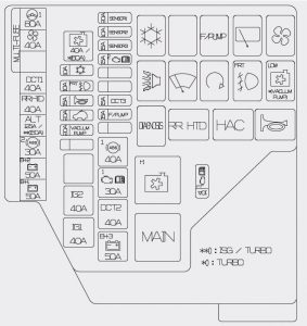
| Fuse | Ampere rating [A] | Fuse name | Symbol | Circuit protected |
| MULTI FUSE | 80 | MDPS | EPS Control Module | |
| 40 | BLOWER | Blower Motor | ||
| 40 | DCT1 | TCM (G4FD-DCT) | ||
| 40 | RR HTD | E/R Fuse & Relay Box (RLY. 15) | ||
| 125 (W/O ISG) | ALT | E/R Fuse & Relay Box (Multi Fuse), Alternator | ||
| 150 (With ISG) | ||||
| 30 | ABS2 | Multipurpose Check Connector, ESP Control Module | ||
| 50 | B+2 | Smart Junction Box(Power Window Relay, ARISU-LT, FUSE – F34, F23) | ||
| 50 | B+1 | Leak Current Autocut Device (Leak Current Autocut Relay, Leak Current Autocut Switch, FUSE – F25, F12, F16), FUSE-F20, F39, F29 | ||
| FUSE | 40 – GDI/MPI | C/FAN | E/R Fuse & Relay Box (RLY. 1, RLY. 4) | |
| 60 – T-GDI | ||||
| 10 | A/CON | E/R Fuse & Relay Box (RLY. 11) | ||
| 10 | FOG LP FRT | E/R Fuse & Relay Box (RLY. 6) | ||
| 15 | HORN | E/R Fuse & Relay Box (RLY. 12, RLY. 13) | ||
| 20 | SUNROOF | Panorama Sunroof Motor | ||
| 40 | IG2 | Ignition Switch, PDM Relay Box (IG 2 Relay), E/R Fuse & Relay Box (RLY. 8) | ||
| 40 | IG1 | Ignition Switch, PDM Relay Box (IG 1 Relay, ACC Relay) | ||
| 20 | SENSOR1 | ECM | ||
| 10 | SENSOR2 | MPI |
Oil Control Valve #1/#2, Purge Control Solenoid Valve, Variable Intake Solenoid Valve, Engine Room Fuse & Relay Box (RLY. 11) | |
| Oil Control Valve #1/#2, Purge Control Solenoid Valve, Variable Intake Solenoid Valve, Engine Room Fuse & Relay Box (RLY. 11), Waste Gate Valve, Recirulation Valve | ||||
| 15 | SENSOR3 | Camshaft Position Sensor (EX)/(IN)(G4FC), Injector #1/#2/#3/#4(G4FC), Oxygen Sensor (UP)/(DOWN), E/R Fuse & Relay Box (RLY. 14) | ||
| 15 | ECU2 | TCM (G4FC), ECM (G4FD) | ||
| 15 | DCT3 | TCM (G4FD-DCT) | ||
| 15 | F/PUMP | E/R Fuse & Relay Box (RLY. 7) | ||
| 40 | ABS1 | ESP Control Module | ||
| 30 | ECU1 | Engine Room Fuse & Relay Box (RLY. 2, FUSE – F23, F33) | ||
| 40 | DCT2 | TCM (G4FD-DCT) | ||
| 50 | B+3 | Smart Junction Box (Tail Lamp Relay, Fuse – F21, F15, F19, F24, F26, ARISU-RT) | ||
| 10 | ECU3 | Sport Mode Switch | ||
| 20 | VACUUM PUMP |
Engine Room Fuse & Relay Box (VACCUM PUMP RELAY) |
WARNING: Terminal and harness assignments for individual connectors will vary depending on vehicle equipment level, model, and market.