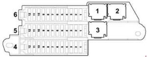
Audi Q7 (2005 – 2015) – fuse box diagram

Year of production: 2005, 2006, 2007, 2008, 2009, 2010, 2011, 2012, 2013, 2014, 2015

Location

Audi Q7 - fuse box diagram - location
Audi Q7 – fuse box diagram – location
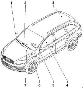
  1. On right in dash panel
  2. Left-hand drive models: in centre of dash panel / Right-hand drive models: in driver’s footwell
  3. On right in luggage compartment
  4. Under driver seat
  5. On left in dash panel
  6. On left in plenum chamber.
  7. In rear left of engine compartment

Fuse assignment in fuse box, left dash panel

Audi Q7 - fuse box diagram - dashboard (left side)
Audi Q7 – fuse box diagram – dashboard (left side)
No. A Function/component
A Not used
B 10 From June 2009: Main fuse for optional equipment -S245-
C Not used
D Not used
Fuse carrier 1
1 5
Up to June 2010: Not used
From June 2010: Voltage stabiliser -J532-
2 5 Up to June 2010: Not used
From June 2010: Relay for automatic anti-dazzle interior mirror -J910-
3 7,5 Up to June 2010: Not used
From June 2010: Control unit for information electronics 1 -J794-
4 5 Up to May 2010: Tyre pressure monitor control unit -J502-
5 20 Auxiliary heater control unit -J364-
6 10 LHD: Driver seat lumbar support adjustment switch -E176-
6 10 RHD: Front passenger seat lumbar support adjustment switch -E177-
7 35 LHD: Driver door control unit -J386-
Driver side window regulator motor -V147-
Rear left door control unit -J388-
Rear left window regulator motor -V26-
7 35 RHD: Front passenger door control unit -J387-
Rear right window regulator motor -V27-
Front passenger side window regulator motor -V148-
8 15 LHD: Driver door control unit -J386-
Rear left door control unit -J388- (up to May 2008)
8 15 RHD: Front passenger door control unit -J387-
Rear right door control unit -J389-
9 5
Up to May 2008: Energy management control unit -J644-
From June 2010: From Tyre pressure monitor control unit -J502-
10 30 LHD: Entry and start authorisation control unit -J518-
Entry and start authorisation switch -E415-
10 5 RHD: Media player in position 1 -R118- (up to June 2009)
Media player in position 2 -R119- (up to June 2009)
CD changer -R41- (up to May 2010)
DVD player -R7- (up to May 2010)

MiniDisc player -R153- (up to June 2009)
Video recorder and DVD player -R129- (up to June 2009)
Connection for external audio sources -R199- (up to June 2009)

11 10 LHD: Steering column electronics control unit -J527-
11 10 RHD: Rear Climatronic operating and display unit -E265-
Rear fresh air blower control unit -J391-
12 5 LHD: Interior monitoring sensor -G273-
Alarm horn -H12-
12 5 RHD: Comfort system central control unit -J393-
Fuse carrier 2
1 Not used
2 Not used
3 15
Up to June 2009: Not used
From June 2009: Front left seat ventilation control unit -J800-
4 30 Wiper motor control unit -J400-
Windscreen wiper motor -V-
5 5 Light/rain sensor -G397-
6 25 Dual tone horn relay -J4-
High tone horn -H2-
Low tone horn -H7-
7 30 LHD: Onboard supply control unit -J519-
7 25 RHD; from June 2010: 12 V socket 3 -U19-
12 V socket 4 -U20-
8 25 LHD: Onboard supply control unit -J519-
8 20 RHD: Cigarette lighter -U1-
9 25 LHD: Onboard supply control unit -J519-
9 25 RHD: 12 V socket -U5-
12 V socket 2 -U18-
10 10 LHD: Control unit in dash panel insert -J285- (up to May 2010)
Data bus diagnostic interface -J533-
Display in dash panel insert -Y24- (up to May 2010)
10 10 RHD: Climatronic control unit -J255-
Fresh air blower control unit -J126-
11 30 Headlight washer system relay -J39-
12 10 16-pin connector -T16-, diagnostic connector
Fuse carrier 3
1 10 Left headlight
2 5 Control unit for adaptive cruise control -J428-
Sensor heater for adaptive cruise control system -Z47-
3 5 Direct sight Japan
display unit -J145-
Display unit button -E506-
Coolant shut-off valve relay -J541-2)
Heater coolant shut-off valve -N279-2)
4 10 Lane departure warning
Lane departure warning control unit -J759-
Windscreen heater for lane departure warning -Z67-
5 10
51)
LHD: Signal system control unit -J616-
Operating unit for special signals -E507-
From November 2007: Preparation for multimedia (9WM)
5 5 RHD; from November 2007: Preparation for multimedia (9WM)
6 5 LHD: Steering column electronics control unit -J527-
Entry and start authorisation control unit -J518-
Light switch -E1-
Comfort system central control unit -J393-
Trailer detector control unit -J345-
Tyre pressure monitor control unit -J502- (7K6) (from June 2008)
6 5 RHD: Heated bench seat cushion for rear left seat -Z10-
Heated backrest for rear left seat -Z11-
Heated bench seat cushion for rear right seat -Z12-
Heated backrest for rear right seat -Z13-
7 5 Oil level and oil temperature sender -G266-
8 5 16-pin connector -T16-, diagnostic connector
9 5 Automatic anti-dazzle interior mirror -Y7-
10 5 Garage door operation control unit -J530-
Garage door operating unit -E284-
11 5 Data bus diagnostic interface -J533-
12 5 Headlight range control regulator -E102-
Left headlight range control motor -V48-
Right headlight range control motor -V49-
12 5 Air quality sensor -G238-
Rear Climatronic operating and display unit -E265-
Climatronic control unit -J255-
1) From November 2007

2) Only for models with 6-cylinder diesel engine, generation 2

Fuse assignment in fuse box, right dash panel
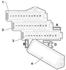
Audi Q7 - fuse box diagram - dashboard (right side)
Audi Q7 – fuse box diagram – dashboard (right side)
No. A Function/component
A 5 Fuse for control unit for structure-borne sound -S348-
B 5 From June 2008: Cool box fuse -S340-
C Not used
D Not used
Fuse carrier 1
1 20 Heated bench seat cushion for rear left seat -Z10-
Heated backrest for rear left seat -Z11-
Heated bench seat cushion for rear right seat -Z12-
Heated backrest for rear right seat -Z13-
2 10 Up to May 2010: Automatic gearbox control unit -J217- (0AT)
2 5 Up to May 2010: Automatic gearbox control unit -J217-
From June 2010: Aerial amplifier for mobile telephone -R86-
Chip card reader control unit -J676-
Telephone bracket -R126-
3 30 Heated seat cushion for front left seat -Z45-
Heated seat cushion for front right seat -Z46-
3 15 RHD; from June 2009: Front right seat ventilation control unit -J799-
4 20 ABS control unit -J104-
5 15 LHD: Front passenger door control unit -J387-
Rear right door control unit -J389- (up to May 2008)
5 15 RHD: Driver door control unit -J386-
Rear left door control unit -J388-
6 25 LHD: 12 V socket 3 -U19-
12 V socket 4 -U20-
6 25 RHD; up to May 2010: 12 V socket 3 -U19-
12 V socket 4 -U20-
6 30 RHD; from June 2010: Onboard supply control unit -J519-
7 10
LHD: Front passenger seat lumbar support adjustment switch -E177-
RHD: Driver seat lumbar support adjustment switch -E176-
8 20 LHD: Cigarette lighter -U1-
8 25 RHD: Onboard supply control unit -J519-
9 25 LHD: 12 V socket -U5-
12 V socket 2 -U18-
9 25 RHD: Onboard supply control unit -J519-
10 10 LHD: Climatronic control unit -J255-
Fresh air blower control unit -J126-
10 10
RHD:
Up to June 2010: Control unit in dash panel insert -J285-

From June 2010: Diagnostic interface for data bus -J533-

11 5 Up to May 2008: Brake light switch -F-
Brake pedal switch -F47-
ABS control unit -J104-
11 15 From June 2010: Refrigerator box -J698-
12 15 Onboard supply control unit 2 -J520-
Fuse carrier 2
1 10 Right headlight
2 5 Adaptive suspension control unit -J197-
3 5 Preparation for mobile telephone (9ZD)
4 5 Lane change assist control unit -J769-
Lane change assist control unit 2 -J770-
5 5 Brake light suppression relay -J508-
Clutch pedal switch -F36-
6 5 Automatic gearbox control unit -J217-
6 20 Automatic gearbox control unit -J217- (09D)
7 5 ABS control unit -J104-
8 5 Multifunction switch -F125-
Tiptronic switch -F189-
Selector lever sensors control unit -J587-
9 5
Control unit for parking aid -J446-
Control unit for overhead view camera -J928- (LHD; from June 2012)
10 5
LHD: Airbag control unit -J234-
RHD: Data bus diagnostic interface -J533-
11 5 LHD: Heated rear left seat switch with regulator -E128-
Heated rear right seat switch with regulator -E129-
11 5 RHD: Steering column electronics control unit -J527-
Entry and start authorisation control unit -J518-
Light switch -E1-
Comfort system central control unit -J393-
Trailer detector control unit -J345-
12 5 LHD: Air quality sensor -G238-
Rear Climatronic operating and display unit -E265-
Climatronic control unit -J255-
12 5 RHD: Headlight range control regulator -E102-
Left headlight range control motor -V48-
Right headlight range control motor -V49-
Fuse carrier 3
1 15 Up to May 2007: Rear window wiper motor -V12-
From June 2008: Cool box -J698-
1 10 From June 2010: Control unit in dash panel insert -J285-
2 5 Up to June 2010: Left washer jet heater element -Z20-
Right washer jet heater element -Z21-
From June 2010: Reversing camera system control unit -J772-
3 30 Up to May 2010: Onboard supply control unit -J519-
3 5 From June 2010: DVD player -R7-
CD changer -R41-
4 5 From June 2009: Display unit for front information display and operating unit control unit -J685-
5 5
Up to June 2009: Telephone transmitter and receiver unit -R36-
Up to May 2010: Telephone bracket -R126-
Chip card reader control unit -J676
5
10
15
From June 2010: Automatic gearbox control unit -J217-
6 15 Up to June 2009: Control unit for front information display and operating unit -J523-
Aerial amplifier -R24-
 6 7.5
Up to June 2009: Control unit for front information display and operating unit -J523-
Up to May 2010: Control unit for information electronics 1 -J794-
6 30 From June 2010: Gearbox hydraulic pump relay -J510- (for models with start/stop system only)
Auxiliary hydraulic pump control unit -J922- (for models with start/stop system only)
7 20 Sliding sunroof adjustment control unit -J245-
8 20 Rear sliding sunroof control unit -J392-
9 20 Sunroof roller blind control unit -J394-
10 5 LHD: Media player in position 1 -R118- (up to May 2009)
Media player in position 2 -R119- (up to May 2009)
DVD player -R7- (up to May 2010)
CD changer -R41- (up to May 2010)
MiniDisc player -R153- (up to May 2009)
Video recorder and DVD player -R129- (up to May 2009)
Connection for external audio sources -R199- (from 2006 November up to May 2009)
10 30 RHD: Entry and start authorisation control unit -J518-
Entry and start authorisation switch -E415-
11 35 LHD: Front passenger side window regulator motor -V148-
Rear right window regulator motor -V27-
11 35 RHD: Driver door control unit -J386-
Driver side window regulator motor -V147-
Rear left door control unit -J388-
Rear left window regulator motor -V26-
12 10 LHD: Rear Climatronic operating and display unit -E265-
Rear fresh air blower control unit -J391-
12 10 RHD: Steering column electronics control unit -J527-

Relay and fuse carrier centre dash panel
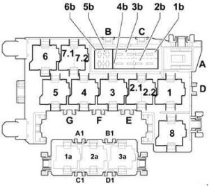
Audi Q7 - fuse box diagram - relay and carrier centre dashboard
Audi Q7 – fuse box diagram – relay and carrier centre dashboard
No. A Function/component
B Not used
C 30 Trailer detector control unit -J345- (only USA)
Brake booster (only USA)
D 30 Control unit for seat adjustment and steering column adjustment with memory function -J136-
Control unit for front passenger seat adjustment with memory function -J521-
E Not used
F Not used
G Not used
1b 40 Fresh air blower -V2-
2b 40 ABS control unit -J104-
3b 40 Rear fresh air blower -V80-
4b 40 Heated rear window -Z1-
5b 15 From June 2007: Rear window wiper motor -V12-
6b 5 From June 2007: Left washer jet heater element -Z20-
Right washer jet heater element -Z21-
A1 Not used
B1 Not used
C1 Not used
D1 Not used
Relay
1 Adaptive suspension compressor relay -J403-
2.1 Terminal 75x voltage supply relay -J694-
2.2 Dual tone horn relay -J4-
3 Headlight washer system relay -J39-
4 Brake light suppression relay -J508-
5 Not used
6 Heated rear window relay -J9-
7.1 V6 TDI/FSI, V8 MPI/FSI, V12 TDI: Continued coolant circulation relay -J151- (V6 FSI from June 2009)
7.1 From June 2010: Coolant shut-off valve relay -J541- (only for models with 6-cylinder diesel engine, generation 2)
7.2 From June 2010: Relay for automatic anti-dazzle interior mirror -J910- (only models with 8-speed automatic gearbox)
8 Gearbox hydraulic pump relay -J510-
1a Not used
2a Not used
3a Not used

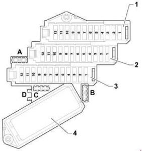
Fuse assignment in fuse box, on right in luggage compartment

Audi Q7 - fuse box diagram - luggage compartment (right side)
Audi Q7 – fuse box diagram – luggage compartment (right side)
No. A Function/component
Fuse carrier 6
1 15
Up to May 2010: Signal system control unit -J616-
From June 2010: Multimedia system control unit -J650-
2 30 Control unit for reducing agent metering system -J880-
3 15 Up to May 2010: Adaptive suspension control unit -J197-
3 5 From June 2012: Reducing agent tank flap switch -F502-
4 5 Up to May 2010: Reversing camera system control unit -J772-
Reversing camera -R189-
5 5 Control unit for parking aid -J446-
6 15 Comfort system central control unit 2 -J773-
7 15 Comfort system central control unit 2 -J773-
8 5 Remote control receiver for auxiliary heater -R64-
9 20 12 V socket 5 -U26-
10 20 Comfort system central control unit -J393-
11 15 Aerial reader unit for keyless entry system -J723-
12 30 Comfort system central control unit -J393-
Fuse carrier 5
1 15 Signal system control unit -J616-
2 5 Operating unit for special signals -E507-
3 15 Two-way radio cut-off relay -J84-
Two-way radio -R8-
4 15 Two-way radio cut-off relay -J84-
Two-way radio -R8-
5 5 Radio -R-
5 15 From June 2010: Signal system control unit -J616-
6 5 Up to June 2009: TV tuner -R78-
7 5 Up to June 2009: Navigation system with CD drive control unit -J401-
8 30 Up to June 2009: Digital sound package control unit -J525-
9 5 Up to June 2009: Digital radio -R147-
10 30 Up to June 2009: Digital sound package control unit 2 -J787-
11 5 Up to June 2009: Reversing camera system control unit -J772-
Up to June 2009: Reversing camera -R189-
12 Not used
Fuse carrier 4
1 5 From June 2009 up to May 2010: Radio -R-
1
7,5
30
From June 2010: Digital sound package control unit -J525-
2  5 From June 2009: TV tuner -R78-
From June 2011: Digital TV tuner -R171-
3 30 From June 2009: Digital sound package control unit -J525-
4 30 From June 2009: Digital sound package control unit 2 -J787-
5 15 Rear Seat Entertainment (9WP, 9WK) (from November 2007 up to May 2010) 
Multimedia system control unit -J650- (up to May 2010)
Adaptive suspension control unit -J197- (from June 2010)
6 20 Comfort system central control unit -J393-
7 30 Rear lid control unit -J605-
Motor in rear lid control unit -V375-
8 30 Rear lid control unit 2 -J756-
Motor in rear lid control unit 2 -V376-
9 15 Trailer detector control unit -J345-
10 15
201)
Trailer detector control unit -J345-
11 15
201)
Trailer detector control unit -J345-
12 30
251)
Trailer detector control unit -J345-
Hinged tow attachment ball head motor -V317-
Relay
1 Not used
2 Not used
3 From November 2007: 6-pin, connector -T6am-, for Rear Seat Entertainment
1) From June 2007

Fuse assignment in fuse box, under driver seat

Audi Q7 - fuse box diagram - under driver's seat` class=`size-medium wp-image-21719` height=`266` loading=`lazy` sizes=`(max-width: 300px) 100vw, 300px` src=`/uploads/778/70a/a25/77870aa2515fbf02900e58b5d0f21b63.jpg` srcset=`/uploads/778/70a/a25/77870aa2515fbf02900e58b5d0f21b63.jpg 300w,  393w` width=`300` />

<figcaption class=`wp-caption-text` id=`caption-attachment-21719`>Audi Q7 – fuse box diagram – under driver’s seat</figcaption>
</figure>

<table class=`table table-hover table-bordered` style=`width: 547px;`>
	<tbody>
		<tr>
			<td align=`center` style=`width: 42px;` width=`35`><b>No.</b></td>
			<td align=`center` style=`width: 43px;` width=`35`><b>A</b></td>
			<td align=`center` style=`width: 452px;`><b>Function/component</b></td>
		</tr>
		<tr>
			<td align=`center` style=`width: 42px;`>2</td>
			<td align=`center` style=`width: 43px;`>–</td>
			<td style=`width: 452px;`>
			<div> </div>

			<p>Battery isolation igniter -N253-</p>
			</td>
		</tr>
		<tr>
			<td align=`center` style=`width: 42px;`>A</td>
			<td align=`center` style=`width: 43px;`>40</td>
			<td style=`width: 452px;`>Self-levelling suspension fuse -S110-</td>
		</tr>
		<tr>
			<td align=`center` style=`width: 42px;`>B1</td>
			<td align=`center` style=`width: 43px;`>30</td>
			<td style=`width: 452px;`><b>From June 2010:</b> Fuse 1 (30) -S204-</td>
		</tr>
		<tr>
			<td align=`center` style=`width: 42px;`>B2</td>
			<td align=`center` style=`width: 43px;`>5</td>
			<td style=`width: 452px;`><b>From June 2008: </b>Fuse for vehicle location system -S347-</td>
		</tr>
		<tr>
			<td align=`center` style=`width: 42px;`>B3</td>
			<td align=`center` style=`width: 43px;`>–</td>
			<td style=`width: 452px;`>Not used</td>
		</tr>
		<tr>
			<td align=`center` style=`width: 42px;`>B4</td>
			<td align=`center` style=`width: 43px;`>30</td>
			<td style=`width: 452px;`><b>From June 2010: </b>Fuse 2 (30) -S205-</td>
		</tr>
		<tr>
			<td align=`center` style=`width: 42px;`>SD1</td>
			<td align=`center` style=`width: 43px;`>150</td>
			<td style=`width: 452px;`>Fuse 1 on fuse holder D -SD1-</td>
		</tr>
		<tr>
			<td align=`center` style=`width: 42px;`>SD2</td>
			<td align=`center` style=`width: 43px;`>125</td>
			<td style=`width: 452px;`><b>Up to May 2006:</b> Fuse 2 on fuse holder D -SD2-</td>
		</tr>
		<tr>
			<td align=`center` style=`width: 42px;` valign=`top`>SD2</td>
			<td align=`center` style=`width: 43px;` valign=`top`>150</td>
			<td style=`width: 452px;` valign=`top`><b>From June 2006:</b> Fuse 2 on fuse holder D -SD2-</td>
		</tr>
		<tr>
			<td align=`center` style=`width: 42px;`>SD3</td>
			<td align=`center` style=`width: 43px;`>50</td>
			<td style=`width: 452px;`>Fuse 3 on fuse holder D -SD3-</td>
		</tr>
		<tr>
			<td align=`center` style=`width: 42px;`>SD4</td>
			<td align=`center` style=`width: 43px;`>60</td>
			<td style=`width: 452px;`>Fuse 4 on fuse holder D -SD4-</td>
		</tr>
		<tr>
			<td align=`center` style=`width: 42px;`>SD5</td>
			<td align=`center` style=`width: 43px;`>125</td>
			<td style=`width: 452px;`>Fuse 5 on fuse holder D -SD5-</td>
		</tr>
		<tr align=`center`>
			<td colspan=`3` style=`width: 537px;`><b>Relay</b></td>
		</tr>
		<tr>
			<td align=`center` style=`width: 42px;`>1</td>
			<td colspan=`2` style=`width: 495px;`>Terminal 15 voltage supply relay -J329-</td>
		</tr>
	</tbody>
</table>

<h3>Relay and fuse carrier in electronics box engine compartment (petrol engine)</h3>

<figure aria-describedby=`caption-attachment-21721` class=`wp-caption alignnone` id=`attachment_21721` style=`width: 300px`><img alt=`Audi Q7 - fuse box diagram - relay and fuse carrier in electronics box engine compartment (petrol engine)` class=`size-medium wp-image-21721` height=`190` loading=`lazy` sizes=`(max-width: 300px) 100vw, 300px` src=`/uploads/6cc/800/2c3/6cc8002c35181fef134aaf7d34a46230.jpg` srcset=`/uploads/6cc/800/2c3/6cc8002c35181fef134aaf7d34a46230.jpg 300w,  449w` width=`300` />

<figcaption class=`wp-caption-text` id=`caption-attachment-21721`>Audi Q7 – fuse box diagram – relay and fuse carrier in electronics box engine compartment (petrol engine)</figcaption>
</figure>

<table class=`table table-hover table-bordered` style=`width: 547px;`>
	<tbody>
		<tr>
			<td align=`center` style=`width: 39px;` width=`35`><b>No.</b></td>
			<td align=`center` style=`width: 39px;` width=`35`><b>A</b></td>
			<td align=`center` style=`width: 459px;`><b>Function/component</b></td>
		</tr>
		<tr>
			<td align=`center` style=`width: 39px;`>1</td>
			<td align=`center` style=`width: 39px;`>
			<div>40</div>

			<div>60</div>
			</td>
			<td style=`width: 459px;`>Radiator fan -V7-</td>
		</tr>
		<tr>
			<td align=`center` style=`width: 39px;`>2</td>
			<td align=`center` style=`width: 39px;`>50</td>
			<td style=`width: 459px;`>Secondary air pump motor -V101-</td>
		</tr>
		<tr>
			<td align=`center` style=`width: 39px;`>3</td>
			<td align=`center` style=`width: 39px;`>–</td>
			<td style=`width: 459px;`>Not used</td>
		</tr>
		<tr>
			<td align=`center` style=`width: 39px;`>4</td>
			<td align=`center` style=`width: 39px;`>
			<div>40</div>

			<div>60</div>
			</td>
			<td style=`width: 459px;`>Radiator fan 2 -V177-</td>
		</tr>
		<tr>
			<td align=`center` style=`width: 39px;`>5</td>
			<td align=`center` style=`width: 39px;`>50</td>
			<td style=`width: 459px;`>Motor for secondary air pump 2 -V189-</td>
		</tr>
		<tr>
			<td align=`center` style=`width: 39px;`>6</td>
			<td align=`center` style=`width: 39px;`>–</td>
			<td style=`width: 459px;`>Not used</td>
		</tr>
		<tr>
			<td align=`center` style=`width: 39px;`>7</td>
			<td align=`center` style=`width: 39px;`>30<br />
			20<sup class=`hochtief`>4)</sup></td>
			<td style=`width: 459px;`>Ignition coils</td>
		</tr>
		<tr>
			<td align=`center` style=`width: 39px;`>8</td>
			<td align=`center` style=`width: 39px;`>5</td>
			<td style=`width: 459px;`>Radiator fan control unit -J293-<br />
			Radiator fan control unit 2 -J671-</td>
		</tr>
		<tr>
			<td align=`center` style=`width: 39px;`>9</td>
			<td align=`center` style=`width: 39px;`>15</td>
			<td style=`width: 459px;`>Engine control unit -J623-<br />
			Injectors</td>
		</tr>
		<tr>
			<td align=`center` style=`width: 39px;`>10</td>
			<td align=`center` style=`width: 39px;`>10</td>
			<td style=`width: 459px;`>High-pressure sender -G65-<sup class=`hochtief`>1) 2) 3)</sup><br />
			Coolant circulation pump -V50-<sup class=`hochtief`>1)</sup><br />
			Map-controlled engine cooling system thermostat -F265-<sup class=`hochtief`>1)</sup><br />
			Continued coolant circulation relay -J151-<sup class=`hochtief`>1)</sup><br />
			Camshaft control valve 1 -N205-<sup class=`hochtief`>1) 2) 3)</sup><br />
			Camshaft control valve 2 -N208-<sup class=`hochtief`>1) 3)</sup><br />
			Intake manifold flap valve -N316-<sup class=`hochtief`>1)</sup><br />
			Exhaust camshaft control valve 1 -N318-<sup class=`hochtief`>1) 2)</sup><br />
			Exhaust camshaft control valve 2 -N319-<sup class=`hochtief`>1)</sup><br />
			Intake manifold flap valve 2 -N403-<sup class=`hochtief`>1)</sup><br />
			Charge air cooling pump -V188-<sup class=`hochtief`>3) only</sup></td>
		</tr>
		<tr>
			<td align=`center` style=`width: 39px;`>11</td>
			<td align=`center` style=`width: 39px;`>5</td>
			<td style=`width: 459px;`>Engine control unit -J623-<br />
			Air mass meter -G70-<sup class=`hochtief`>2) only</sup></td>
		</tr>
		<tr>
			<td align=`center` style=`width: 39px;`>12</td>
			<td align=`center` style=`width: 39px;`>5</td>
			<td style=`width: 459px;`>Crankcase breather heater element -N79-</td>
		</tr>
		<tr>
			<td align=`center` style=`width: 39px;`>13</td>
			<td align=`center` style=`width: 39px;`>15</td>
			<td style=`width: 459px;`>Air mass meter -G70-<sup class=`hochtief`>1)</sup><br />
			Air mass meter 2 -G246-<sup class=`hochtief`>1)</sup><br />
			Activated charcoal filter solenoid valve 1 -N80-<sup class=`hochtief`>1) 2)</sup><br />
			Secondary air inlet valve -N112-<sup class=`hochtief`>1) 3)</sup><br />
			Fuel metering valve -N290-<sup class=`hochtief`>1) 2)</sup><br />
			Intake manifold flap valve -N316-<sup class=`hochtief`>2) 3)</sup><br />
			Secondary air inlet valve 2 -N320-<sup class=`hochtief`>1) 3)</sup><br />
			Fuel metering valve 2 -N402-<sup class=`hochtief`>1)</sup><br />
			Oil pressure control valve -N428-<sup class=`hochtief`>3)</sup><br />
			Continued coolant circulation pump -V51-<sup class=`hochtief`>3)</sup><br />
			Fuel system diagnostic pump -V144-<sup class=`hochtief`>1) 2) 3)</sup><br />
			Crankcase breather system shut-off valve -N548-<sup class=`hochtief`>3) only</sup></td>
		</tr>
		<tr>
			<td align=`center` style=`width: 39px;`>14</td>
			<td align=`center` style=`width: 39px;`>15</td>
			<td style=`width: 459px;`>Lambda probe -G39-<br />
			Lambda probe 2 -G108-</td>
		</tr>
		<tr>
			<td align=`center` style=`width: 39px;`>15</td>
			<td align=`center` style=`width: 39px;`>15</td>
			<td style=`width: 459px;`>Lambda probe downstream of catalytic converter -G130-<br />
			Lambda probe 2 downstream of catalytic converter -G131-</td>
		</tr>
		<tr>
			<td align=`center` style=`width: 39px;`>16</td>
			<td align=`center` style=`width: 39px;`>30</td>
			<td style=`width: 459px;`>Fuel pump control unit -J538-</td>
		</tr>
		<tr>
			<td align=`center` style=`width: 39px;`>17</td>
			<td align=`center` style=`width: 39px;`>5</td>
			<td style=`width: 459px;`>Engine control unit -J623-</td>
		</tr>
		<tr>
			<td align=`center` style=`width: 39px;`>18</td>
			<td align=`center` style=`width: 39px;`>15</td>
			<td style=`width: 459px;`>Vacuum pump for brakes -V192-<sup class=`hochtief`>1) 2)</sup></td>
		</tr>
		<tr align=`center`>
			<td colspan=`3` style=`width: 537px;`><b>Relay</b></td>
		</tr>
		<tr>
			<td align=`center` style=`width: 39px;`>A1</td>
			<td colspan=`2` style=`width: 498px;`>Starter motor relay -J53-<sup>5)</sup><br />
			Engine component current supply relay -J757-<sup><sup>6)</sup></sup></td>
		</tr>
		<tr>
			<td align=`center` style=`width: 39px;`>A2</td>
			<td colspan=`2` style=`width: 498px;`>Starter motor relay 2 -J695-<sup>5)</sup><br />
			Motronic current supply relay -J271-<sup>6)</sup></td>
		</tr>
		<tr>
			<td align=`center` style=`width: 39px;`>A3</td>
			<td colspan=`2` style=`width: 498px;`>Engine component current supply relay -J757-<sup>5)</sup></td>
		</tr>
		<tr>
			<td align=`center` style=`width: 39px;`>A4</td>
			<td colspan=`2` style=`width: 498px;`>Secondary air pump relay -J299-<sup>1,3)</sup></td>
		</tr>
		<tr>
			<td align=`center` style=`width: 39px;`>A5</td>
			<td colspan=`2` style=`width: 498px;`>Brake servo relay -J569-<sup>5)</sup><br />
			Starter motor relay -J53-<sup>6)</sup></td>
		</tr>
		<tr>
			<td align=`center` style=`width: 39px;`>A6</td>
			<td colspan=`2` style=`width: 498px;`>Continued coolant circulation relay -J151-<sup>5)</sup><br />
			Starter motor relay 2 -J695-<sup>6)</sup></td>
		</tr>
		<tr>
			<td align=`center` style=`width: 39px;`>B1</td>
			<td colspan=`2` style=`width: 498px;`>Not used</td>
		</tr>
		<tr>
			<td align=`center` style=`width: 39px;`>B2</td>
			<td colspan=`2` style=`width: 498px;`>Not used</td>
		</tr>
		<tr>
			<td align=`center` style=`width: 39px;`>B3</td>
			<td colspan=`2` style=`width: 498px;`>Fuel pump relay -J17-<sup>5)</sup></td>
		</tr>
		<tr>
			<td align=`center` style=`width: 39px;`>B4</td>
			<td colspan=`2` style=`width: 498px;`>Not used</td>
		</tr>
		<tr>
			<td align=`center` style=`width: 39px;`>B5</td>
			<td colspan=`2` style=`width: 498px;`>Fuel cooling pump relay -J445-<sup>5)</sup></td>
		</tr>
		<tr>
			<td align=`center` style=`width: 39px;`>B6</td>
			<td colspan=`2` style=`width: 498px;`>Not used</td>
		</tr>
		<tr>
			<td align=`center` style=`width: 39px;`>C1</td>
			<td colspan=`2` style=`width: 498px;`>Circulation pump relay -J160-<sup>1)</sup><br />
			Brake servo relay -J569-<sup>2)</sup><br />
			Auxiliary coolant pump relay -J496-<sup>3)</sup></td>
		</tr>
		<tr>
			<td align=`center` style=`width: 39px;` valign=`top`>C2</td>
			<td colspan=`2` valign=`top`>Motronic current supply relay -J271-<sup>5)</sup></td>
		</tr>
		<tr>
			<td colspan=`3` style=`width: 39px;`>1) For engine code BAR only<br />
			2) For engine codes BHK, BHL only<br />
			3) For engine codes CJTC, CJTB, CJWB, CNAA, CJWC, CTWA, CTWB, CJWE only<br />
			4) From June 2010<br />
			5) Up to June 2009<br />
			6) From June 2009</td>
		</tr>
	</tbody>
</table>

<h3>Relay and fuse carrier in electronics box engine compartment (diesel engine)</h3>

<figure aria-describedby=`caption-attachment-21723` class=`wp-caption alignnone` id=`attachment_21723` style=`width: 300px`><img alt=`Audi Q7 - fuse box diagram - relay and fuse carrier in electronics box engine compartment (diesel engine)` class=`size-medium wp-image-21723` height=`190` loading=`lazy` sizes=`(max-width: 300px) 100vw, 300px` src=`/uploads/dad/f3c/34f/dadf3c34fffc84040eba16286c84d1cb.jpg` srcset=`/uploads/dad/f3c/34f/dadf3c34fffc84040eba16286c84d1cb.jpg 300w,  449w` width=`300` />

<figcaption class=`wp-caption-text` id=`caption-attachment-21723`>Audi Q7 – fuse box diagram – relay and fuse carrier in electronics box engine compartment (diesel engine)</figcaption>
</figure>

<table class=`table table-hover table-bordered` style=`width: 547px;`>
	<tbody>
		<tr>
			<td align=`center` style=`width: 39px;` width=`35`><b>No.</b></td>
			<td align=`center` style=`width: 59px;` width=`35`><b>A</b></td>
			<td align=`center` style=`width: 433px;`><b>Function/component</b></td>
		</tr>
		<tr>
			<td align=`center` style=`width: 39px;`>1</td>
			<td align=`center` style=`width: 59px;`>60</td>
			<td style=`width: 433px;`>Radiator fan control unit -J293-<br />
			Radiator fan -V7-</td>
		</tr>
		<tr>
			<td align=`center` style=`width: 39px;`>2</td>
			<td align=`center` style=`width: 59px;`>80</td>
			<td style=`width: 433px;`>Automatic glow period control unit -J179-</td>
		</tr>
		<tr>
			<td align=`center` style=`width: 39px;`>3</td>
			<td align=`center` style=`width: 59px;`>40</td>
			<td style=`width: 433px;`>Heater element for auxiliary air heater -Z35- (400 W)<sup class=`hochtief`>4) 11) 13)</sup></td>
		</tr>
		<tr>
			<td align=`center` style=`width: 39px;`>4</td>
			<td align=`center` style=`width: 59px;`>40<sup class=`hochtief`>1)</sup><br />
			60<sup class=`hochtief`>2)</sup></td>
			<td style=`width: 433px;`>Radiator fan control unit 2 -J671-<br />
			Radiator fan 2 -V177-</td>
		</tr>
		<tr>
			<td align=`center` style=`width: 39px;`>5</td>
			<td align=`center` style=`width: 59px;`>80<br />
			60<sup class=`hochtief`>13)15)</sup></td>
			<td style=`width: 433px;`>Glow period control unit 2 -J703-<sup class=`hochtief`>3) 5) 6) 10)</sup><br />
			Relay for 3rd heat setting -J959-<sup class=`hochtief`>13) 15)</sup></td>
		</tr>
		<tr>
			<td align=`center` style=`width: 39px;`>6</td>
			<td align=`center` style=`width: 59px;`>80<br />
			60<sup class=`hochtief`>13)15)</sup></td>
			<td style=`width: 433px;`>Heater element for auxiliary air heater -Z35- (2 x 400 W)<sup class=`hochtief`>4) 11)</sup></td>
		</tr>
		<tr>
			<td align=`center` style=`width: 39px;`>7</td>
			<td align=`center` style=`width: 59px;`>15</td>
			<td style=`width: 433px;`>Map-controlled engine cooling system thermostat -F265-<sup class=`hochtief`>9) 13)</sup><br />
			Automatic glow period control unit -J179-<br />
			Throttle valve module -J338-<sup class=`hochtief`>4) 5) 8) 11)</sup><br />
			Low heat output relay -J359-<sup class=`hochtief`>4) 11) 13)</sup><br />
			High heat output relay -J360-<sup class=`hochtief`>4) 11) 13)</sup><br />
			Turbocharger 1 control unit -J724-<sup class=`hochtief`>7)</sup><br />
			Turbocharger 2 control unit -J725-<sup class=`hochtief`>6)</sup><br />
			Control unit for charge air cooler bypass -J865-<sup class=`hochtief`>4) 11)</sup><br />
			Exhaust gas recirculation valve -N18-<sup class=`hochtief`>7)</sup><br />
			Exhaust gas recirculation cooler changeover valve -N345-<br />
			Exhaust gas recirculation cooler changeover valve 2 -N381-<sup class=`hochtief`>4) 11)</sup><br />
			Electro-hydraulic engine mounting solenoid valve -N398-<sup class=`hochtief`>9) 13)</sup><br />
			Oil pressure control valve -N428-<sup class=`hochtief`>3) 4) 9) 10) 11) 13)</sup><br />
			Cylinder head coolant valve -N489-<sup class=`hochtief`>9) 10) 13)</sup><br />
			Intake manifold flap motor -V157-<sup class=`hochtief`>6) 7)</sup><br />
			Motor for intake manifold flap 2 -V275-<sup class=`hochtief`>7) only</sup></td>
		</tr>
		<tr>
			<td align=`center` style=`width: 39px;`>8</td>
			<td align=`center` style=`width: 59px;`>5</td>
			<td style=`width: 433px;`>Radiator fan control unit -J293-<br />
			Radiator fan control unit 2 -J671-</td>
		</tr>
		<tr>
			<td align=`center` style=`width: 39px;`>9</td>
			<td align=`center` style=`width: 59px;`>15</td>
			<td style=`width: 433px;`>Engine control unit -J623-<br />
			Engine control unit 2 -J624-<sup class=`hochtief`>3) 5) 6) 10)</sup></td>
		</tr>
		<tr>
			<td align=`center` style=`width: 39px;`>10</td>
			<td align=`center` style=`width: 59px;`>10</td>
			<td style=`width: 433px;`>Fuel pressure regulating valve -N276-<br />
			Fuel metering valve -N290-<br />
			Fuel metering valve 2 -N402-<sup class=`hochtief`>5)</sup><br />
			Fuel pressure regulating valve 2 -N484-<sup class=`hochtief`>5) only</sup></td>
		</tr>
		<tr>
			<td align=`center` style=`width: 39px;`>11</td>
			<td align=`center` style=`width: 59px;`>15<br />
			10<sup class=`hochtief`>9) 11)</sup></td>
			<td style=`width: 433px;`>Lambda probe -G39-<br />
			Lambda probe 2 -G108-<sup class=`hochtief`>3) 5) 6) 10)</sup><br />
			Lambda probe heater -Z19-<br />
			Lambda probe 2 heater -Z28-<sup class=`hochtief`>3) 5) 6) 10)</sup></td>
		</tr>
		<tr>
			<td align=`center` style=`width: 39px;`>12</td>
			<td align=`center` style=`width: 59px;`>10<br />
			5<sup class=`hochtief`>4) 14)</sup></td>
			<td style=`width: 433px;`>Fuel cooling pump relay -J445-<sup class=`hochtief`>3) 5) 6)</sup><br />
			NOx sender control unit -J583-<sup class=`hochtief`>4) 13)</sup><br />
			NOx sender 2 control unit -J881-<sup class=`hochtief`>4) 11) 13)</sup><br />
			Fuel cooling pump -V166-<sup class=`hochtief`>3) 6)</sup><br />
			Exhaust gas recirculation cooler pump -V400-<sup class=`hochtief`>3) 5) 10)</sup><br />
			vacant <sup class=`hochtief`>7) 8) 9)</sup><br />
			Particle sensor -G784-<sup class=`hochtief`>13) only</sup></td>
		</tr>
		<tr>
			<td align=`center` style=`width: 39px;`>13</td>
			<td align=`center` style=`width: 59px;`>10<br />
			15<sup class=`hochtief`>4) 5)</sup></td>
			<td style=`width: 433px;`>High-pressure sender -G65-<br />
			Continued coolant circulation relay -J151-<br />
			Fuel cooling pump relay -J445-<sup class=`hochtief`>4) 7) 8)</sup><br />
			Glow period control unit 2 -J703-<sup class=`hochtief`>3) 5) 6) 10)</sup><br />
			Exhaust gas recirculation cooler change-over valve 2 -N381-<sup class=`hochtief`>5)</sup><br />
			Coolant circulation pump -V50-<br />
			Continued coolant circulation pump -V51-<sup class=`hochtief`>4) 8) 10) 11)</sup><br />
			Fuel cooling pump -V166-<sup class=`hochtief`>4) 7) 8)</sup><br />
			Motor for intake manifold flap 2 -V275-<sup class=`hochtief`>6)</sup><br />
			Exhaust gas recirculation cooler pump -V400-<sup class=`hochtief`>4) 8)</sup></td>
		</tr>
		<tr>
			<td align=`center` style=`width: 39px;`>14</td>
			<td align=`center` style=`width: 59px;`>5</td>
			<td style=`width: 433px;`>Air mass meter -G70-<br />
			Air mass meter 2 -G246-<sup class=`hochtief`>3) 5) 6) 10)</sup></td>
		</tr>
		<tr>
			<td align=`center` style=`width: 39px;`>15</td>
			<td align=`center` style=`width: 59px;`>5</td>
			<td style=`width: 433px;`>Engine control unit -J623-<br />
			Engine control unit 2 -J624-<sup class=`hochtief`>3) 5) 6) 10)</sup></td>
		</tr>
		<tr>
			<td align=`center` style=`width: 39px;`>16</td>
			<td align=`center` style=`width: 59px;`>20<br />
			25</td>
			<td style=`width: 433px;`>Fuel system pressurisation pump -G6-<br />
			Fuel pump control unit -J538-<sup class=`hochtief`>9) 10) 13)</sup></td>
		</tr>
		<tr>
			<td align=`center` class=`cellborderright` style=`width: 39px;` valign=`top`>17</td>
			<td align=`center` style=`width: 59px;`>20</td>
			<td style=`width: 433px;`>Fuel pump -G23-<sup class=`hochtief`>5) 6) 7) 8)</sup></td>
		</tr>
		<tr>
			<td align=`center` class=`cellborderright` style=`width: 39px;` valign=`top`> </td>
			<td align=`center` style=`width: 59px;`>10</td>
			<td style=`width: 433px;`>Pressure sender for reducing agent metering system -G686-<sup class=`hochtief`>4)</sup><br />
			Reducing agent pump -V437-<sup class=`hochtief`>4)</sup><br />
			Heater for reducing-agent pump -Z103-<sup class=`hochtief`>4) only</sup></td>
		</tr>
		<tr>
			<td align=`center` style=`width: 39px;`> </td>
			<td align=`center` style=`width: 59px;`>5</td>
			<td style=`width: 433px;`>Engine control unit -J623-<sup class=`hochtief`>9) 10) 11) 13)</sup><br />
			Engine control unit 2 -J624-<sup class=`hochtief`>10) only</sup></td>
		</tr>
		<tr>
			<td align=`center` class=`cellborderright` style=`width: 39px;` valign=`top`>18</td>
			<td align=`center` style=`width: 59px;`>7.5</td>
			<td style=`width: 433px;`>Crankcase breather heater element -N79-<sup class=`hochtief`>3) 5) 6) 10)</sup><br />
			Crankcase breather heater element 2 -N483-<sup class=`hochtief`>3) 5) 10)</sup></td>
		</tr>
		<tr>
			<td align=`center` class=`cellborderright` style=`width: 39px;` valign=`top`> </td>
			<td align=`center` style=`width: 59px;`>20</td>
			<td style=`width: 433px;`>Relay for supplementary fuel pump -J832-<sup class=`hochtief`>4) 8)</sup><br />
			Supplementary fuel pump -V393-<sup class=`hochtief`>4) 8)</sup></td>
		</tr>
		<tr>
			<td align=`center` style=`width: 39px;`> </td>
			<td align=`center` style=`width: 59px;`>10<br />
			5<sup class=`hochtief`>12)</sup></td>
			<td style=`width: 433px;`>Pressure sender for reducing agent metering system -G686-<sup class=`hochtief`>11) 13)</sup><br />
			Reducing agent pump -V437-<sup class=`hochtief`>11) 13)</sup><br />
			Heater for reducing-agent pump -Z103-<sup class=`hochtief`>11) 13)</sup></td>
		</tr>
		<tr align=`center`>
			<td colspan=`3` style=`width: 531px;`><b>Relay</b></td>
		</tr>
		<tr>
			<td align=`center` style=`width: 39px;`>A1</td>
			<td colspan=`2` style=`width: 492px;`>Automatic glow period control unit -J179-</td>
		</tr>
		<tr>
			<td align=`center` style=`width: 39px;`>A2</td>
			<td colspan=`2` style=`width: 492px;`><b>Up to June 2009; V12: </b>Starter motor relay -J53-<br />
			<b>From June 2009:</b> Terminal 30 voltage supply relay -J317-</td>
		</tr>
		<tr>
			<td align=`center` style=`width: 39px;`>A3</td>
			<td colspan=`2` style=`width: 492px;`><b>CCGA, CCFA, CCFC, V12:</b> Glow period control unit 2 -J703-</td>
		</tr>
		<tr>
			<td align=`center` style=`width: 39px;`>A4</td>
			<td colspan=`2` style=`width: 492px;`><b>Up to June 2009; V12: </b>Starter motor relay 2 -J695-<br />
			<b>From June 2009; CCMA, CATA</b>: Relay for supplementary fuel pump -J832-</td>
		</tr>
		<tr>
			<td align=`center` style=`width: 39px;`>A5</td>
			<td colspan=`2` style=`width: 492px;`><b>Up to June 2009: </b>Not used<br />
			<b>From June 2009:</b> Starter motor relay -J53-</td>
		</tr>
		<tr>
			<td align=`center` style=`width: 39px;`>A6</td>
			<td colspan=`2` style=`width: 492px;`><b>Up to June 2009: </b>Relay for supplementary fuel pump -J832-<br />
			<b>From June 2009:</b> Starter motor relay 2 -J695-</td>
		</tr>
		<tr>
			<td align=`center` style=`width: 39px;`>B1</td>
			<td colspan=`2` style=`width: 492px;`><b>CCMA, CATA, CLZB, CNRB:</b> Low heat output relay -J359-</td>
		</tr>
		<tr>
			<td align=`center` style=`width: 39px;`>B2</td>
			<td colspan=`2` style=`width: 492px;`>Not used</td>
		</tr>
		<tr>
			<td align=`center` style=`width: 39px;`>B3</td>
			<td colspan=`2` style=`width: 492px;`><b>Up to June 2009: </b>Fuel pump relay -J17-<br />
			<b>From June 2009; CLZB, CNRB</b>: Relay for 3rd heat setting -J959-</td>
		</tr>
		<tr>
			<td align=`center` style=`width: 39px;`>B4</td>
			<td colspan=`2` style=`width: 492px;`><b>CCMA, CATA, CLZB, CNRB:</b> High heat output relay -J360-</td>
		</tr>
		<tr>
			<td align=`center` style=`width: 39px;`>B5</td>
			<td colspan=`2` style=`width: 492px;`><b>Up to June 2009; V12: </b>Fuel cooling pump relay -J445-<br />
			<b>From June 2009; </b><b>CCFA</b>: Fuel pump relay for auxiliary heater -J749-</td>
		</tr>
		<tr>
			<td align=`center` style=`width: 39px;`>B6</td>
			<td colspan=`2` style=`width: 492px;`><b>CCGA, V12:</b> Auxiliary coolant pump relay -J496-</td>
		</tr>
		<tr>
			<td align=`center` style=`width: 39px;`>C1</td>
			<td colspan=`2` style=`width: 492px;`><b>Up to June 2009; V12: </b>Fuel pump relay for auxiliary heater -J749-<br />
			<b>From June 2009; </b><b>CCMA, CATA, CCFA</b>: Fuel cooling pump relay -J445</td>
		</tr>
		<tr>
			<td align=`center` style=`width: 39px;` valign=`top`>C2</td>
			<td colspan=`2` valign=`top`><b>Up to June 2009; V12: </b>Terminal 30 voltage supply relay -J317-<br />
			<b>From June 2009; </b><b>CCFA</b>: Fuel pump relay -J17-</td>
		</tr>
		<tr>
			<td colspan=`3` style=`width: 39px;`>1) Models without trailer towing attachment<br />
			2) Models with trailer towing attachment<br />
			3) For engine code CCFA<br />
			4) For engine codes CCMA, CATA, up to May 2010<br />
			5) For engine code CCGA<br />
			6) For engine code BTR<br />
			7) For engine codes BUN, BUG<br />
			8) For engine codes CASA, CASB<br />
			9) For engine codes CJGA, CJMA, CJGC, CJGD, CRCA, CNRA<br />
			10) For engine code CCFC<br />
			11) For engine codes CCMA, CATA, from June 2010<br />
			12) From June 2010<br />
			13) For engine codes CLZB, CNRB<br />
			14) Models without particle sensor<br />
			15) From June 2012 </td>
		</tr>
	</tbody>
</table>

<h3>Terminal 30 wiring junction 2 -TV22-/slave start socket -U6-</h3>

<figure aria-describedby=`caption-attachment-21725` class=`wp-caption alignnone` id=`attachment_21725` style=`width: 236px`><img alt=`Audi Q7 - fuse box diagram - Terminal 30 wiring junction 2 -TV22-/slave start socket -U6` class=`size-medium wp-image-21725` height=`300` loading=`lazy` sizes=`(max-width: 236px) 100vw, 236px` src=`/uploads/eb5/cae/590/eb5cae59091c5bc53f6ca60546d38617.jpg` srcset=`/uploads/eb5/cae/590/eb5cae59091c5bc53f6ca60546d38617.jpg 236w,  354w` width=`236` />

<figcaption class=`wp-caption-text` id=`caption-attachment-21725Audi Q7 – fuse box diagram – Terminal 30 wiring junction 2 -TV22-/slave start socket -U6

WARNING: Terminal and harness assignments for individual connectors will vary depending on vehicle equipment level, model, and market.

Discussão