Hyundai Azera (2016 – 2017) – fuse box diagram
Year of production: 2016, 2017
Instrument panel (Driver’s side fuse panel)
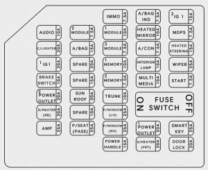
instrument panel
| Number | Ampere rating [A] | Symbol | Protected component |
| 1 | 7,5 | IMMO | Smart Key Control Module |
| 2 | 7,5 | A/BAG IND | Instrument Cluster |
| 3 | 20 | SPARE | — |
| 4 | 10 | AUDIO | AMP, Smart Key Control Module, Telematics Unit,E/R Junction Block (Power Outlet Relay), A/V & Navigation Head Unit,Front Monitor (Audio/Navigation), Audio, A/C Control Module |
| 5 | 7,5 | MODULE 2 | ESC Control Module, Rear Seat Warmer LH/RH, Console Switch, A/C Control Module, Rear Power Window Switch LH/RH, Driver IMS Module, Rear Parking Assist Sensor LH/RH/LH(Center)/RH(Center) |
| 6 | 10 | MODULE 1 | Driver Power Seat Switch, Driver/Passenger Seat Warmer Module, Driver/Passenger Door Module, Stop Lamp Switch, Crash Pad Switch, Driver/Passenger CCS Control Module, Steering Tilt & Telescope Module, Instrument Cluster, Blind Spot Detection Radar LH/RH, Multifunction Switch, Forward Collision Warning Unit, Lane Departure Warning Unit, Electro Chromic Mirror, ATM Lever Indicator, Tire Pressure Monitoring Module, Telematics Unit |
| 7 | 10 | HTD MIRR | Driver/Passenger Power Outside Mirror, A/C Control Module |
| 8 | 7,5 | MDPS | MDPS Unit |
| 9 | 20 | C/LIGHTER | Center Tray Outlet |
| 10 | 15 | A/BAG | SRS Control Module, Passenger Occupant Detection Sensor, A/C Control Module |
| 11 | 7,5 | MODULE 3 | Smart Key Control Module, Rear Seat Warmer LH/RH |
| 12 | 7,5 | A/CON | A/C Control Module, E/R Junction Block (Blower Relay), Driver/Passenger Seat Warmer Module, Active Incar Sensor, Driver/Passenger CCS Control Module |
| 13 | 15 | IG1 2 | Steering Wheel Heater |
| 14 | 20 | IG1 1 | E/R Junction Block (ECU 5 10A, ECU 4 10A) |
| 15 | 10 | MEMORY 1 | Driver Power Seat Switch, Data Link Connector, A/C Control Module, Driver/Passenger Door Module, Instrument Cluster, Tire Pressure Monitoring Module, Auto Light & Photo Sensor |
| 16 | 10 | INTERIOR LAMP | Rear Door Lamp LH/RH, MAP Lamp, Garnish Lamp LH/RH, Driver/Passenger Door Mood Lamp, Driver/Passenger Door Lamp, Driver/Passenger Foot Lamp, Driver/Passenger Door Scuff Lamp, Rear Door Mood Lamp LH/RH, Vanity Lamp Switch LH/RH, Rear Door Scuff Lamp LH/RH, Trunk Room Lamp, Rear Personal Lamp Center/LH/RH |
| 17 | 25 | WIPER | Wiper Motor, E/R Junction Block (Washer Relay, Wiper (LO) Relay, Wiper (HI) Relay) |
| 18 | 10 | STOP LAMP | Smart Key Control Module, Stop Lamp Switch, Start Stop Button Switch |
| 19 | 7,5 | MEMORY 2 | RF Receiver |
| 20 | 10 | MULTI MEDIA | Front Monitor (Audio/Navigation), A/V & Navigation Head Unit, Telematics Unit, Audio |
| 21 | 7,5 | START | Transaxle Range Switch, PCM |
| 22 | 20 | SUNROOF | Panorama Sunroof |
| 23 | 10 | TRUNK | Trunk Lid Relay, Fuel Filler Door & Trunk Lid Switch |
| 24 | 10 | S/HEATER RR | Rear Seat Warmer LH/RH |
| 25 | 10 | DRV P/SEAT | — |
| 26 | 25 | P/ WDW LH | Driver Safety Window Module, Rear Power Window Switch LH |
| 27 | 25 | AMP | AMP |
| 28 | 25 | PASS P/SEAT | Passenger Reclining Limit Switch, Power Seat Relay Box RH |
| 29 | 25 | P/WDW RH | Passenger Safety Window Module, Rear Power Window Switch RH |
| 30 | 25 | SMART KEY | Smart Key Control Module |
| 31 | 15 | P/HANDLE | Sport Mode Switch, Steering Tilt & Telescopic Module |
| 32 | 20 | S/HEATER FRT | Driver/Passenger Seat Warmer Module, Driver/Passenger CCS Control Module |
| 33 | 20 | DR LOCK | Door Lock/Unlock Relay, ICM Relay Box (Two Turn Unlock Relay) |
Engine compartment fuse panel
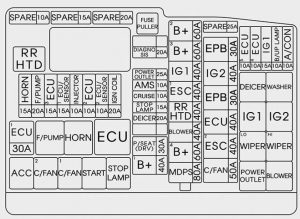
| Number | Ampere rating [A] | Symbol | Protected component | |
| MULTI FUSE | 1 | 60 | B+2 | Smart Junction Box (P/HANDLE 15A, SUNROOF 20A, DRV P/SEAT 10A, PASS P/SEAT 25A, IPS 2, ARISU-LT 1) |
| 2 | 60 | B+3 | Smart Junction Box (P/WDW 25A, P/WDW RH 25A, S/HEATER FRT 10A, TRUNK 10A, P/OUTLET 1 20A) | |
| 3 | 40 | IG1 | PDM 1 (ACC) Relay, PDM 2 (IG1) Relay | |
| 4 | 40 | ESC1 | ESC Module | |
| 5 | 40 | RR HTD | RR HTD Relay | |
| 6 | 40 | BLOWER | Blower Relay | |
| 7 | 60 | B+4 | Smart Junction Block (STOP LAMP 10A, S/HEATER RR 20A, IPS 3/4, ARISU-LT 2, AMP 25A, P/OUTLET 2 20A) | |
| 8 | 80 | MDPS | MDPS Unit | |
| FUSE | 9 | 10 | A/CON | A/C Control Module |
| 10 | 10 | B/UP LAMP | Rear Combination Lamp (IN) LH/RH, Electro Chromic Mirror, Audio, Front Monitor | |
| 11 | 10 | ECU 4 | PCM, IDB(Injector Driver Box) | |
| 12 | 10 | ECU 5 | Multipurpose Check Connector | |
| 13 | 30 | EPB 2 | Electronic Parking Brake Module | |
| 14 | 40 | IG 2 | Start Relay, PDM 3 (IG2) Relay | |
| 15 | 30 | EPB 1 | Electronic Parking Brake Module | |
| 16 | 40 | B+5 | EMS Block (ECU 3 15A, ECU 1 30A, F/PUMP 20A, HORN 15A) | |
| 17 | 40 | ESC 2 | ESC Module | |
| 18 | 50 | C/FAN | C/Fan Relay | |
| 19 | 20 | DIAGNOSIS | Multipurpose Check Connector | |
| 20 | 10 | AMS | Battery Sensor | |
| 21 | 10 | CRUISE | Smart Cruise Control Radar | |
| 22 | 15 | STOP LAMP | Stop Signal Electronic Module | |
| 23 | 20 | DEICER | Deicer Relay | |
| 24 | 30 | DRV P/SEAT | Driver Lumbar Support Limit Switch, Driver IMS Module, Power Seat Relay Box LH, Driver Reclining Limit Switch | |
| 25 | 40 | B+1 | Smart Junction Box (DR LOCK 20A, SMART KEY 1 25A, Leak Current Autocut Device (Leak Current Autocut Relay, Leak Current Autocut Switch, IPS 5)) | |
| 26 | 20 | IGN COIL | Ignition Coil #1~#6, Condenser #1/#2 | |
| 27 | 10 | SENSOR 2 | IDB (Injector Driver Box), PCM, Purge Control Solenoid Valve, Oil Control Valve #1 ~ #4, Variable Intake Solenoid Valve #1, #2, Canister Close Valve, E/R Junction (C/FAN Relay) | |
| 28 | 10 | ECU 2 | IDB (Injector Driver Box) | |
| 29 | 10 | INJECTOR | PCM, EMS Box (F/Pump Relay) | |
| 30 | 15 | SENSOR 1 | PCM, Oxygen Sensor #1~#4 | |
| 31 | 15 | ECU 3 | PCM, IDB (Injector Driver Box) | |
| 32 | 20 | F/PUMP | EMS Block (F/Pump Relay) | |
| 33 | 15 | HORN | EMS Block (Horn Relay), ICM Relay Box(Burglar Horn Relay) | |
| 34 | 30 | ECU 1 | EMS Block (Engine Control Relay) | |
WARNING: Terminal and harness assignments for individual connectors will vary depending on vehicle equipment level, model, and market.