Mazda 3 (2010) – fuse box diagram
Year of production: 2010
Fuse block (Engine compartment)
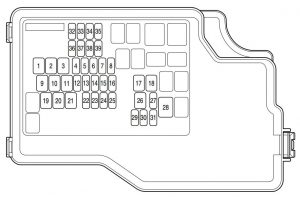
engine compartment
| Position | Description | Fuse rating [A] | Protected component |
| 1 | FAN 2 | — | — |
| 2 | ENG MAIN | 40 | Engine control system |
| 3 | BTN 1 | 50 | For protection of various circuits |
| 4 | A/C MAG | 7,5 | Air conditioner |
| 5 | H/L HI | 20 | Headlight high beam |
| 6 | FOG | 15 | Fog lights* |
| 7 | H/L WASH | — | — |
| 8 | SUNROOF | 15 | Moonroof* |
| 9 | F.DEF RH | — | — |
| 10 | F.DEF LH | — | — |
| 11 | FAN 1 | 40 | Cooling fan |
| 12 | ROOM | 15 | Interior lights |
| 13 | TCM | 15 | TCM* |
| 14 | DSC | 20 | Dynamic Stability Control system* |
| 15 | BTN 2 | 7,5 | For protection of various circuits |
| 16 | AT PUMP | — | — |
| 17 | HEATER | 40 | Heater |
| 18 | INJ | — | — |
| 19 | R.DEF | 30 | Rear window defroster |
| 20 | IGKEY 2 | 40 | For protection of various circuits |
| 21 | IGKEY 1 | 40 | For protection of various circuits |
| 22 | HORN | 15 | Horn |
| 23 | STOP | 15 | Brake lights |
| 24 | ENG+B | 10 | Engine control system |
| 25 | FUEL PUMP | 25 | Fuel system |
| 26 | ABS | 40 | ABS |
| 27 | SEAT WARM | 20 | Seat warmer* |
| 28 | EHPAS | 80 | Electro-Hydraulic Power Assist Steering |
| 29 | — | — | — |
| 30 | ABS IG | 7,5 | ABS |
| 31 | — | — | — |
| 32 | H/L LO RH | 15 | Headlight low beam (RH) |
| 33 | H/L LO LH | 15 | Headlight low beam (LH) |
| 34 | ILLUM | 7,5 | Dashboard illumination |
| 35 | TAIL | 15 | Tail lamp |
| 36 | ENG INJ | 15 | Engine control system |
| 37 | ENG BAR | 15 | PCM |
| 38 | ENG BAR 2 | 20 | PCM |
| 39 | ETV | 15 | Electric throttle valve |
| * Some models | |||
Fuse block (Passenger’s side)
WARNING: Terminal and harness assignments for individual connectors will vary depending on vehicle equipment level, model, and market.