Volvo V60 Plug-in Hybrid (2014 – 2018) – fuse box diagram
Year of production: 2014, 2015, 2016, 2017, 2018
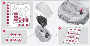
Fuses – engine compartment
A – Engine compartment, upper
B – Engine compartment, front
C – Engine compartment, lower
| Position | Function | Ampere rating [A] |
| 1 | — | — |
| 2 | Primary fuse for the central electronic module (CEM) under the glovebox | 50 |
| 3 | — | 60 |
| 4 | Primary fuse for relay/fuse box under the glovebox | 60 |
| 5 | — | — |
| 6 | — | — |
| 7 | — | — |
| 8 | 2014: Heated windscreen, lefthand side | 40 |
| 9 | Windshield wipers | 30 |
| 10 | Parking heater | 25 |
| 11 | — | — |
| 12 | 2014: Heated windscreen, righthand side | 40 |
| 13 | ABS pump | 40 |
| 14 | ABS valves | 20 |
| 15 | Headlight washers | 20 |
| 16 | Headlamp levelling, Active Xenon headlamps – ABL | 10 |
| 17 | Primary fuse for the central electronic module (CEM) under the glovebox | 20 |
| 18 | ABS | 5 |
| 19 | Speed related power steering | 5 |
| 20 | Engine control module, Transmission control module, Airbags | 10 |
| 21 | Heated washer nozzles | 10 |
| 22 | — | — |
| 23 | Headlamp control | 5 |
| 24 | — | — |
| 25 | — | — |
| 26 | — | — |
| 27 | Relay coils | 5 |
| 28 | Auxiliary lights | 20 |
| 29 | Horn | 15 |
| 30 | Relay coil in main relay for engine management system, Engine control module | 10 |
| 31 | Transmission control module | 15 |
| 32 | — | — |
| 33 | Relay coils in central electrical unit in engine compartment cold zone, Relay coil in relay for coolant pump | 5 |
| 34 | Starter relay | 30 |
| 35 | Glow control module | 10 |
| 36 | Engine Control Module (ECM) | 15 |
| 37 | Mass air flow sensor, Control valves | 15 |
| 38 | Valves, Oil level sensor | 10 |
| 39 | Lambda-sonds; Control module, radiator roller cover | 15 |
| 40 | Diesel filter heater | 20 |
| 41 | 2014: Crankcase ventilation heater | 5 |
| 2015-2018: Crankcase ventilation heater | 10 | |
| 42 | Glow plugs | 70 |
| 43 | Cooling fan | 80 |
| 44 | Electro-hydraulic power steering | 100 |
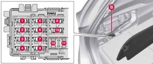
Behind the engine
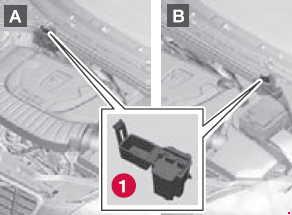
A. Left-hand drive car
B. Right-hand drive car
| Position | Function | Ampere ratting [A] |
| 1 | Monitoring of vacuum pump for brake system | 5 |
Fuse box in the glovebox
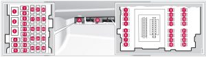
Fusebox A: General fuses
Fusebox B: Control module fuses
Positions: fusebox A
| Position | Function | Ampere ratting [A] |
| 1 | Primary fuse for audio control module, Primary fuse for fuses 16-20 | 40 |
| 2 | 2015-2018: Windscreen washers; Rear window washer | 25 |
| 3 | — | — |
| 4 | — | — |
| 5 | — | — |
| 6 | Door handles, keyless system | 5 |
| 7 | — | — |
| 8 | Control panel, driver’s door | 20 |
| 9 | Control panel, front passenger door | 20 |
| 10 | Control panel, rear passenger door, right | 20 |
| 11 | Control panel, rear passenger door, left | 20 |
| 12 | Keyless | 7,5 |
| 13 | Power seat driver’s side | 20 |
| 14 | Power seat passenger side | 20 |
| 15 | 2014: Windscreen washers, Rear window washer | 25 |
| 16 | Infotainment Control Module or Screen | 5 |
| 17 | Audio control module, TV, Digital radio | 10 |
| 18 | Audio control module or Control module Sensus | 15 |
| 19 | Telephone, Bluetooth™ | 5 |
| 20 | — | — |
| 21 | Sun roof, interior lighting roof, climate sensor, damper motors air intake | 5 |
| 22 | 12 V socket, tunnel console | 15 |
| 23 | Seat heating, rear passenger side right | 15 |
| 24 | Seat heating, rear passenger side left | 15 |
| 25 | Electric additional heater | 15 |
| 26 | Seat heating, front passenger side | 15 |
| 27 | Seat heating, front driver’s side | 15 |
| 28 | Parking assistance, Parking camera, Towbar control module, BLIS, Electrically-driven heater | 5 |
| 29 | — | — |
| 30 | — | — |
Positions: fusebox B
| Position | Function | Ampere ratting [A] |
| 1 | Rear window wiper | 15 |
| 2 | — | — |
| 3 | Interior lighting, Driver’s door control panel, power windows, Power seats, front, Remote controlled garage door opener | 7,5 |
| 4 | Combined instrument panel | 5 |
| 5 | Adaptive cruise control, ACC; collision warning system | 10 |
| 6 | Interior lighting; Rain sensor | 7,5 |
| 7 | Steering wheel module | 7,5 |
| 8 | Central locking system, fuel filler flap | 10 |
| 9 | Heated steering wheel | 15 |
| 10 | 2014-2016: Heated windscreen | 15 |
| 11 | Unlocking, tailgate | 10 |
| 12 | 2013-2018: Folding head restraint | 10 |
| 13 | Fuel pump | 20 |
| 14 | Movement detector for alarm, Climate panel | 5 |
| 15 | Steering lock | 15 |
| 16 | Siren, Data link connector OBDII | 5 |
| 17 | — | — |
| 18 | Airbag | 10 |
| 19 | Collision warning system | 5 |
| 20 | Accelerator pedal sensor; Dimming interior rearview mirror; Seat heating, rear | 7,5 |
| 21 | Infotainment control module (Performance), Audio (Performance) | 15 |
| 22 | Brake lights | 5 |
| 23 | Sunroof | 20 |
| 24 | Immobilizer | 5 |
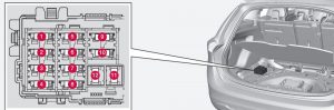
Fuses – in cargo area (No.1)
| Position | Function | Ampere ratting [A] |
| 1 | Electric parking brake, left | 30 |
| 2 | Electric parking brake, right | 30 |
| 3 | Rear window defroster | 30 |
| 4 | Trailer socket 2 | 15 |
| 5 | — | — |
| 6 | 12-volt socket in trunk | 15 |
| 7 | — | — |
| 8 | — | — |
| 9 | — | — |
| 10 | — | — |
| 11 | Trailer socket 1 | 40 |
| 12 | — | — |
Fuses – in cargo area (No.2)
| Position | Function | Ampere ratting [A] |
| 1 | Coolant pump 1 for hybrid battery Valve for coolant pumps 1 and 2 |
10 |
| 2 | Coolant pump 2 for hybrid battery | 10 |
| 3 | Charging unit Voltage converter 400 V-12 V Control module for hybrid battery |
5 |
| 4 | Coolant pump for the cooling system’s low temperature circuit | 15 |
| 5 | Charging unit Voltage converter 400 V-12 V Control module for hybrid battery |
10 |
| 6 | Relay coils; high voltage converter for electric motor and integrated starter generator | 10 |
| 7 | Disengaging the electric motor from the rear axle | 15 |
| 8 | — | — |
| 9 | High voltage converter for electric motor and integrated starter generator; control module for hybrid battery | 10 |
| 10 | Coolant valves for the cooling system’s low temperature circuit Electric A/C compressor Valve for heat exchanger Valve for climate control system |
10 |
| 11 | — | — |
| 12 | — | — |
Fuses – in the engine compartment’s cold zone
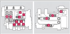
| Position | Function | Ampere rating [A] |
| A1 | Circuit breaker: central electrical module in the engine compartment | 175 |
| A2 | Main fuse for central electronic module (CEM) under the glovebox, relay/fuse box under the glovebox, central electrical unit in cargo area | 175 |
| 1 | Vacuum pump for brake system | 40 |
| 2 | Primary fuse for the central electronic module (CEM) under the glovebox | 50 |
| 3 | Primary fuse for relay/fuse box under the glovebox | 60 |
| 4 | Primary fuse for central electrical unit B in cargo area | 60 |
| 5 | Primary fuse for central electrical unit A in cargo area | 60 |
| 6 | Ventilation fan | 40 |
| 7 | — | — |
| 8 | — | — |
| 9 | — | — |
| 10 | — | — |
| 11 | Oil pump automatic gearbox | 30 |
| 12 | — | — |
WARNING: Terminal and harness assignments for individual connectors will vary depending on vehicle equipment level, model, and market.