Mazda 6 (2011 – 2013) – fuse box diagram
Year of production: 2011, 2012, 2013
Fuse block (Engine compartment)
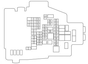
engine compartment
| Position | Description | Fuse rating [A] | Protected component |
| 1 | M.DEF | 10 | Mirror defroster* |
| 2 | ST SIG | 5 | Starter sig |
| 3 | ABS SOL | 30 | DSC |
| 4 | P.WIND (P) | — | – |
| 5 | P.SEAT (P) | 30 | Power seat* |
| 6 | SUN ROOF | 15 | Moonroof* |
| 7 | TAIL | 15 | BCM, Tail lamp |
| 8 | P.OUTLET (R) | 15 | Accessory sockets |
| 9 | AUDIO | 30 | Audio system (Bose® Sound System-equipped model) |
| 10 | ABS MOTOR | 60 | DSC |
| 11 | P.WIND (D) | 40 | Power window |
| 12 | DEFOG | 20 | Rear window defroster |
| 13 | SEAT HEAT | 20 | Seat heat* |
| 14 | A/C | 10 | Air conditioner |
| 15 | FOG | 15 | Fog lights* |
| 16 | BLOWER 2 | — | — |
| 17 | FAN | 60 | Cooling fan |
| 18 | P.SEAT (D) | 30 | Power seat* |
| 19 | BTN | 30 | For protection of various circuits |
| 20 | IG KEY2 | 40 | Starting system |
| 21 | BLOWER | 40 | Blower motor |
| 22 | FUEL PUMP | 26 | Fuel pump |
| 23 | ENGINE2 | 15 | Engine control system* |
| 24 | EGI INJ | 15 | Injector |
| 25 | PCM | 10 | Engine control system |
| 26 | ENGINE | 10*1 | Engine control system |
| 20*2 | |||
| 27 | IG | 20 | For protection of various circuits* |
| 28 | TCM | 20 | TCM* |
| 29 | ESCL | 10 | Electronic steering lock* |
| 30 | IG KEY1 | 40 | For protection of various circuits |
| 31 | MAIN | 125 | For protection of all circuits |
| 32 | DRL | 20 | DRL* |
| 33 | HAZARD | 10 | Hazard warning flashers |
| 34 | ENG+B | 10 | PCM |
| 35 | STOP | 10 | Brake lights |
| 36 | HORN | 15 | Horn |
| 37 | HEAD HI RH | 15 | Headlight-high beam (Right)* |
| 38 | HEAD LO RH | 10 | Headlight-low beam (Right) |
| 39 | HEAD HI LH | 15 | Headlight-high beam (Left)* |
| 40 | HEAD LO LH | 10 | Headlight-low beam (Left) |
| *1 2.5-liter engine
*2 3.7-liter engine |
|||
Fuse block (Passenger’s side)
WARNING: Terminal and harness assignments for individual connectors will vary depending on vehicle equipment level, model, and market.