Mazda MX-5 (2016) – fuse box diagram
Year of production: 2016
Fuse block (Engine compartment)
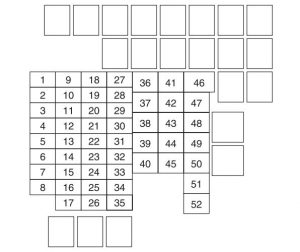
engine compartment
| Position | Description | Fuse rating [A] | Protected component |
| 1 | ENG IG3 | 5 | — |
| 2 | ENG IG2 | 5 | — |
| 3 | HORN2 | 7,5 | Horn |
| 4 | C/U IG1 | 15 | For protection of various circuits |
| 5 | ENG IG1 | 7,5 | Engine control system |
| 6 | — | — | — |
| 7 | INTERIOR | 15 | Overhead light |
| 8 | ENG+B | 7,5 | Engine control system |
| 9 | AUDIO2 | 15 | Audio system |
| 10 | METER1 | 10 | Instrument cluster |
| 11 | SRS1 | 7,5 | Air bag |
| 12 | — | — | — |
| 13 | RADIO | 7,5 | Audio system |
| 14 | ENGINE3 | 20 | Engine control system |
| 15 | ENGINE1 | 10 | Engine control system |
| 16 | ENGINE2 | 15 | Engine control system |
| 17 | AUDIO1 | 25 | Audio system |
| 18 | A/C MAG | 7,5 | Air conditioner |
| 19 | AT PUMP | 20 | Transmission control system* |
| 20 | AT | 15 | Transmission control system* |
| 21 | D LOCK | 25 | Power door locks |
| 22 | H/L RH | 20 | Headlight (RH) |
| 23 | ENG+B2 | 7,5 | Engine control system |
| 24 | TAIL | 20 | Taillights, License plate lights, Parking lights |
| 25 | DRL | 15 | — |
| 26 | ROOM | 25 | Overhead light |
| 27 | FOG | 15 | — |
| 28 | H/CLEAN | 20 | — |
| 29 | STOP | 10 | Brake lights |
| 30 | HORN | 15 | Horn |
| 31 | H/L LH | 20 | Headlight (LH) |
| 32 | ABS/DSC S | 30 | ABS, Dynamic stability control system |
| 33 | HAZARD | 15 | Hazard warning À ashers, Turn signal lights |
| 34 | FUEL PUMP | 15 | Fuel system |
| 35 | ENG+B3 | 5 | — |
| 36 | WIPER | 20 | Windshield wipers |
| 37 | CABIN+B | 50 | For protection of various circuits |
| 38 | — | — | — |
| 39 | — | — | — |
| 40 | ABS/DSC M | 50 | ABS, Dynamic stability control system |
| 41 | EVVT A/R PUMP | 20 | Engine control system |
| 42 | EVPS | 30 | Brake control system |
| 43 | FAN1 | 30 | Cooling fan |
| 44 | FAN2 | 40 | — |
| 45 | ENG.MAIN | 40 | Engine control system |
| 46 | EPS | 60 | Power steering system |
| 47 | DEFOG | 30 | Rear window defogger |
| 48 | IG2 | 30 | For protection of various circuits |
| 49 | INJECTOR | 30 | Engine control system |
| 50 | HEATER | 40 | Air conditioner |
| 51 | — | — | — |
| 52 | — | — | — |
| * Some models | |||
Fuse block (Left side)
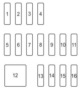
left side
| Position | Description | Fuse rating [A] | Protected component |
| 1 | RHT R | 30 | — |
| 2 | RHT L | 30 | — |
| 3 | — | — | — |
| 4 | — | — | — |
| 5 | F.OUTLET | 15 | Accessory sockets |
| 6 | — | — | — |
| 7 | AT IND | 7,5 | AT shift indicator * |
| 8 | MIRROR | 7,5 | Power control mirror |
| 9 | R_DECK R | 30 | — |
| 10 | R_DECK L | 30 | — |
| 11 | F.WASHER | 15 | Windshield washer |
| 12 | P.WINDOW | 30 | Power windows |
| 13 | — | — | — |
| 14 | SRS2/ESCL | 15 | — |
| 15 | SEAT WARM | 20 | Seat warmer* |
| 16 | M.DEF | 7,5 | Mirror defogger* |
| * Some models | |||
WARNING: Terminal and harness assignments for individual connectors will vary depending on vehicle equipment level, model, and market.