Ford Thunderbird (1994 – 1997) – fuse box diagram
Year of production: 1994, 1995, 1996, 1997
The instrument panel fuse panel
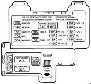
| Fuse | A | Description |
| Run | 5 | • Cluster • Defrost switch • Coolant level sensor • Washer level sensor • DRL module • EVO test • EVO steering sensor • ARC (EVO) module • ARC switch • EATC blend door • Air bag module • Overdrive cancel switch • Brake shift solenoid |
| Anti-Lock | 10 | • Main ABS relay • ABS module |
| OBD-II | 10 | • OBD-II test connector |
| Panel Lps. | 5 | • Cluster illumination • Rear defrost switch illumination • A/? switch-manual illumination • PRND21 illumination • Ashtray light • EATC illumination • Clock illumination • Radio illumination |
| Cigar Ltr. | 20 | • Lighter • Flash to pass |
| Stop/Haz. | 15 | • Speed control module • ABS module • Brake shift interlock • High mount brake lamp • Stop lamps • Flashers |
| Cluster | 5 | • Cluster (gauges) • Cluster (ABS) • Cluster (air bags) • Chime • Autolamp sensor |
| ACC | 10 | • Integrated module • Voltmeter • Speed control • Remote keyless entry module • Anti-theft • Power window and lock switch illumination • Radio • Power antenna • Clock |
| Wipers | 30 | • Wiper motor • Washer motor |
| Seat/Lock | 20 | • Power locks • Decklid release solenoid • Power seats |
| Power Wdo | 20 | • Power windows • Moon roof motor |
| Park Lps. | 10 | • Panel dimmer • Front parking lamps • Parking lamps • License lamps • Autoshock module • Clock |
| Air Bag | 10 | • Air bag module |
| A/C | 10 | • A/? clutch |
| Hego | 15 | • HEGO 1 and 2 |
| Int. Lps. | 10 | • Power mirrors • Anti-theft lamp • Trunk lamp • Map lamps • Vanity lamps • Glove compartment lamp • Engine compartment lamp • Instrument panel lamps • Rear courtesy lamps • Door courtesy lamps • Dome lamp |
| Turn Sig | 10 | • Indicators • Turn signals • Backup lamps |
The high current fuse panel
The high current fuse panel is located in the engine compartment on the left-hand fender apron.
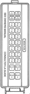
| Fuse | A | Description |
| 1 STD | 15 | DRL module |
| 2 STD | 5 | Memory |
| 3 FL | 20 | Ignition coil |
| 4 FL | 20 | Autoshock |
| 5 FL | 60 | Engine fan |
| 6 FL | 40 | ABS motor |
| 7 FL | 60 | Headlamps |
| 8 FL | 20 | ABS module |
| 9 FL | 60 | Ignition switch |
| 10 STD | 15 | Horn |
| 11 STD | 15 | Generator |
| 12 FL | 40 | Fuse panel |
| 13 FL | 20 | Fuel pump |
| 14 FL | 40 | Rear defrost |
| 15 FL | 20 | Electronic engine control (EEC) module |
| 16 FL | 30 | Pusher fan |
| 17 FL | 60 | Blower motor |
| 18 FL | – | Not Used |
| Relay 1 | – | Not Used |
| Relay 2 | – | Not Used |
| Relay 3 | – | Horn |
| Relay 4 | – | ABS |
| Mega Fuse | 175 | Power distribution box |
WARNING: Terminal and harness assignments for individual connectors will vary depending on vehicle equipment level, model, and market.